Section 03 ENGINE
Sub-Section 07 (ROTARY VALVE)
03-07-2
GENERAL
The following verification procedures such as
clearance of rotary valve cover or rotary valve
shaft gear backlash can be performed without re-
moving engine from watercraft.
However engine must be removed from water-
craft to work on rotary valve shaft/components.
Refer to ENGINE 03-03 for engine removal proce-
dure.
Bottom end must be opened to remove rotary
valve shaft. Refer to ENGINE 03-06.
INSPECTION ON WATERCRAFT
Remove carburetor(s). Refer to FUEL SYSTEM
05-04.
NOTE:
On the 717D engine (SP model), rotary
valve cover and carburetor are removed as an as-
sembly.
1, Rotary Valve Cover
Unscrew 4 screws
no. 2
and withdraw rotary
valve cover and valve
no. 13
.
Rotary Valve/Cover Clearance
The clearance between the rotary valve and the
cover must be 0.30 ± 0.05 mm (.012 ± .002 in).
NOTE:
If the clearance is below 0.25 mm (.010 in)
this could create an overheating situation and if
the clearance is over 0.35 mm (.014 in) this could
create a hard starting situation.
There is two methods to verify rotary valve
/cover clearance. One with a 45° feeler gauge, the
other one with a solder.
45
°
FEELER GAUGE METHOD
Remove O-ring from rotary valve cover.
Remove intake manifold from rotary valve cover
(except 787 engine).
Reinstall cover in place WITHOUT its O-ring and
torque screws to 20 N•m (15 lbf•ft).
Feeler gauge blade from 0.25 mm (.010 in) to 0.35
mm (.014 in) thickness should fit between rotary
valve and cover.
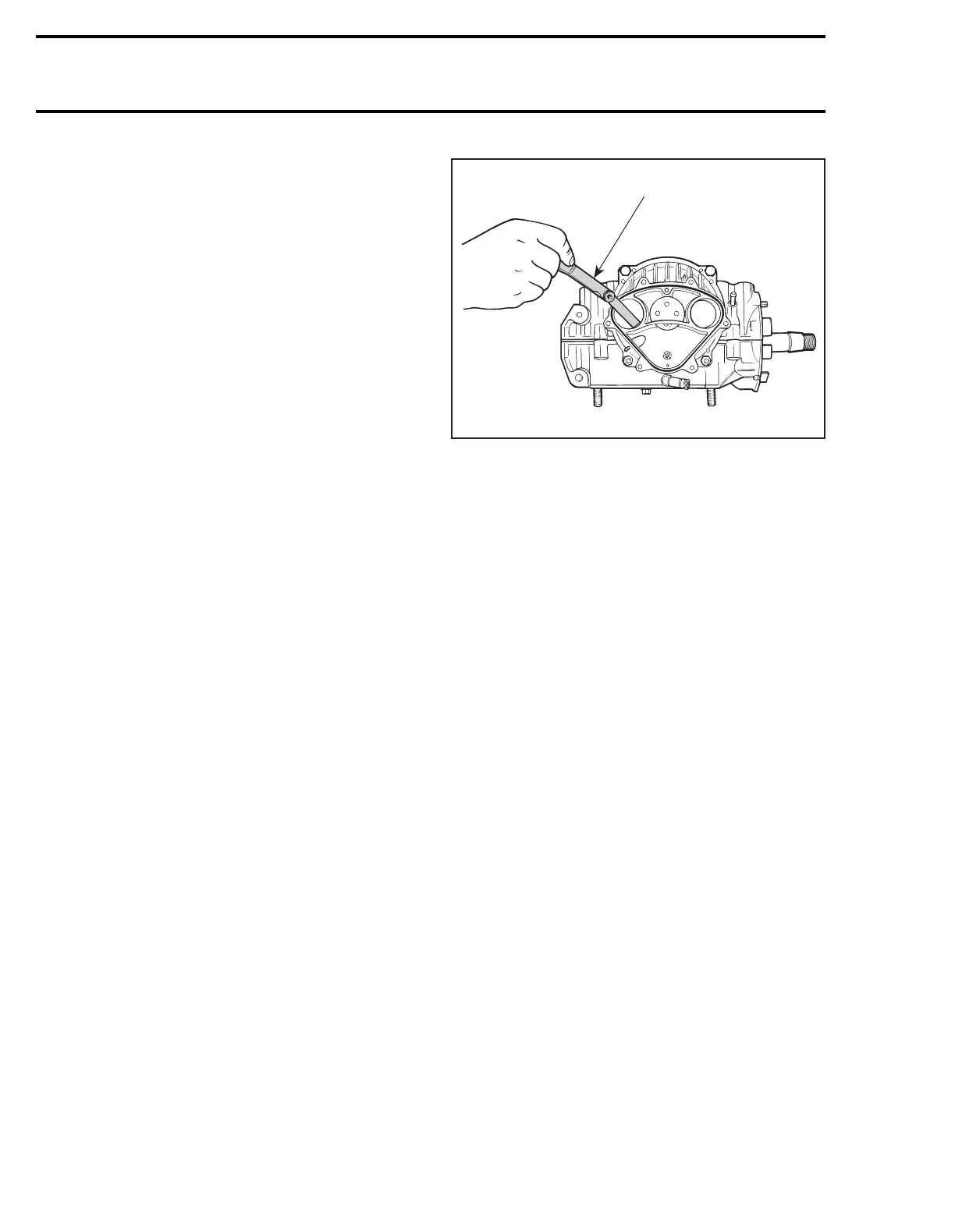
Insert feeler gauge blade through cover inlet ports
to verify clearance. At least verify clearance at two
different places in each port.
1. 45
°
feeler gauge
If rotary valve cover clearance is out of specifica-
tion, machine rotary valve cover seating surface
or replace the cover.
SOLDER METHOD
Remove O-ring from rotary valve cover.
Use the following type of solder:
– rosin core
–diameter: 0.8 mm (.032 in)
– electronic application (available at electronic
stores)
Install two solder pieces of 13 mm (1/2 in) long
directly on rotary valve, one above and one below
rotary valve gear. Apply grease to hold solder in
position.
Reinstall cover in place WITHOUT its O-ring and
torque screws to 20 N•m (15 lbf•ft).
Remove cover then clean and measure compressed
solder thickness, it must be within the specified tol-
erance 0.30 ± 0.05 mm (.012 ± .002 in).
F01D53A
1