Section 03 ENGINE
Sub-Section 06 (BOTTOM END)
03-06-3
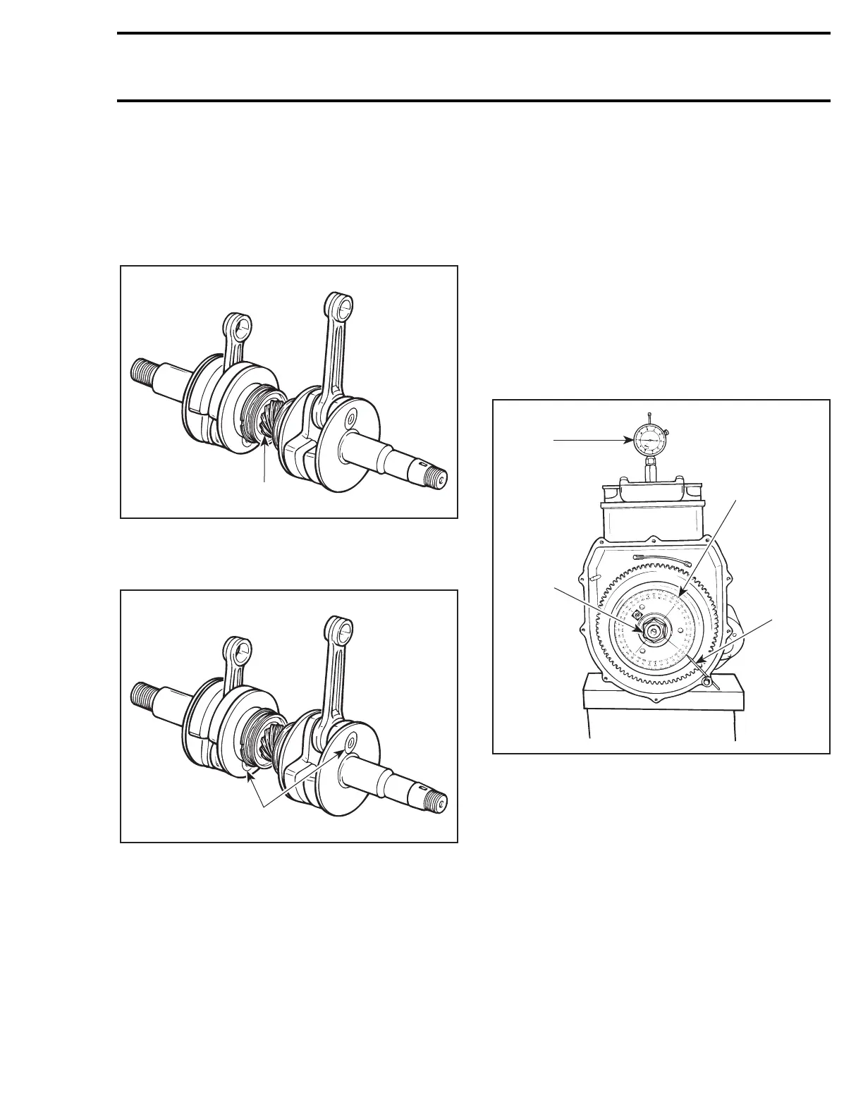
CRANKSHAFT MISALIGNMENT
AND DEFLECTION
Since it is an assembled crankshaft it can become
misaligned or deflected. Crankshaft can be twist-
ed on center main journal, changing timing of one
cylinder in relation with the other.
1. Main journal alignment here
Counterweights can also be twisted on connect-
ing rod journal on any or both cylinder(s).
1. Connecting rod journal alignment here
Crankshaft Alignment at Center Main
Journal
NOTE:
The following checks can be performed
with engine in watercraft without overhauling en-
gine.
To accurately check if crankshaft is twisted on
center main journal, proceed as follows:
– Remove magneto housing cover.
– Remove flywheel nut (and magneto rotor for
the 787 engine). Refer to ENGINE 03-04 for
procedures.
– Install Bombardier degree wheel (P/N 295 000
007) on crankshaft end. Hand-tighten nut only.
– Remove both spark plugs.
– Install a TDC gauge in spark plug hole on
MAG
side
.
– Bring
MAG
piston at Top Dead Center.
– As a needle pointer, secure a wire with a cover
screw and a washer.
– Rotate degree wheel (NOT crankshaft) so that
needle pointer reads 360°.
1. TDC gauge
2. Degree wheel
3. Hand tighten nut
4. Needle pointer
– Remove TDC gauge and install on
PTO side
.
– Bring
PTO
piston at Top Dead Center.
Interval between cylinders must be exactly 180°
therefore, needle pointer must indicate 180° on
degree wheel (360° - 180° = 180°).
Any other reading indicates a misaligned crank-
shaft.
F01D1NA
1
F01D1NB
1
1
F01D4IA
3
2
4