Section 06 LUBRICATION SYSTEM
Sub-Section 03 (OIL INJECTION PUMP)
06-03-4
4, Intake Manifold
Install intake manifold to rotary valve cover and
torque screws
no. 6
to 10 N•m (89 lbf•
in
).
TYPICAL
A. 10 N•m (89 lbf•in)
787 Engine
10,11, Oil Injection Pump and Shaft
Install shaft
no. 11
in crankshaft end.
Install pump. Secure with flat washers
no. 9
and
screws
no. 8
. Torque to 3 N•m (26 lbf•
in
).
Install oil injection pump cable.
ADJUSTMENTS
Preliminary Synchronization
NOTE:
To check synchronization of pump as a
routine maintenance, refer to
Final Synchroniza-
tion
. Make sure idle speed of engine is properly
adjusted.
Ensure carburetor butterfly(ies) is (are) in closed
position.
NOTE:
On a twin carburetor engine, make sure
carburetors are properly synchronized. If neces-
sary, refer to FUEL SYSTEM 05-04.
Turn idle speed screw until it contacts stopper.
Turn idle speed screw 2 turns.
Turn cable adjustment nut to align marks on
pump.
NOTE:
A mirror may be used to facilitate this ver-
ification.
717 Engines
TYPICAL
1. Jam nut
2. Adjustment nut
3. Aligned marks
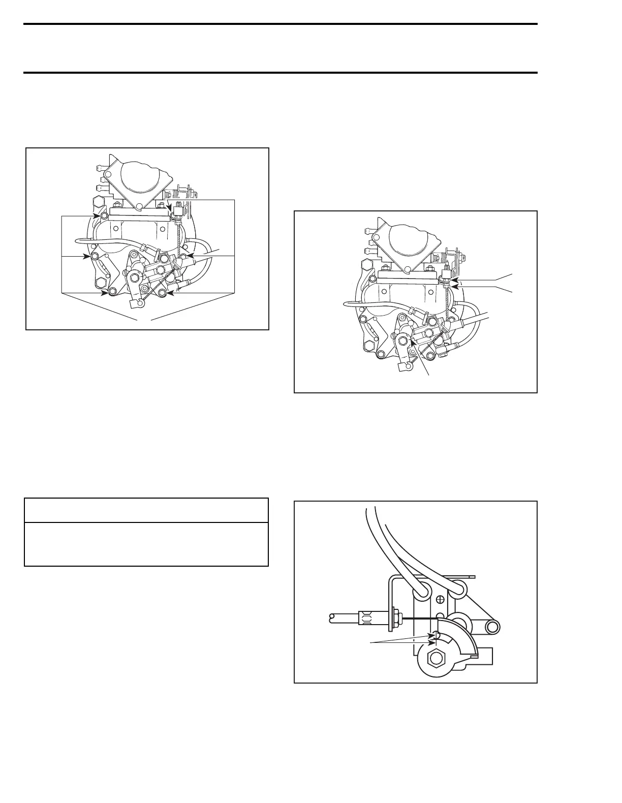
787 Engine
NOTE:
The adjustment screw and jam nut for the
oil injection pump cable are located at PTO carbu-
retor lever.
TYPICAL
1. Aligned marks
-
CAUTION
As oil injection pump adjustment is depen-
dent on throttle cable position, make sure to
perform throttle cable adjustment first.
F01D4RC
A
F01D4RE
2
3
1
F01G0RA
1