Section 13 WIRING DIAGRAMS
Sub-Section 01 (WIRING DIAGRAMS)
13-01-1
WIRING DIAGRAMS 0
WIRE COLOR CODES
First color of a wire is the main color. Second color
is the tracer.
Example: YELLOW/BLACK is a YELLOW wire
with a BLACK tracer.
WIRE DIGIT CODES
GS, GSI, GSX, GTI and XP Models
First number indicates in which connector the
wire is plugged in.
Second number indicates the position of the wire
in the connector.
The letter at the end of the number (if applicable)
indicates a common circuit in the MPEM printed
circuit with another wire bearing the same letter.
Example: 2-18 (g)
The first number indicates that the wire is posi-
tioned in the connector
no. 2
of the MPEM.
The second number indicates that the wire is po-
sitioned in the terminal
no. 18
.
The letter (g) indicates a common circuit with an-
other wire(s) bearing the same letter (g) in the cir-
cuit.
WIRE TERMINAL REMOVAL
To remove terminal from connector housing, use
Snap-on TT600-4 tool.
AMP CONNECTOR
GS, GSI, GSX, GTI and XP Models
These connectors are found on the MPEM of the
aforementioned watercraft.
Description
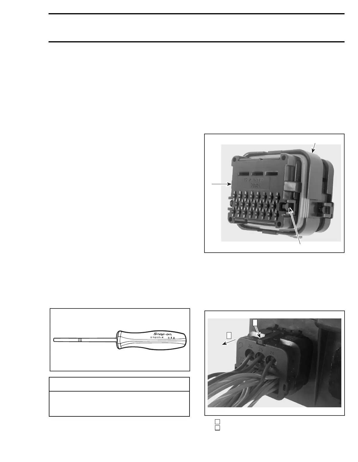
PLUG CONNECTOR
1. Housing
2. Wedge lock
3. Locking tab
Removal
To remove the plug connector from the header as-
sembly, press both tabs and pull plug.
Step : Press tabs (both sides)
Step : Pull plug
◆
WARNING
Ensure all terminals are properly crimped on
wires and connector housings are properly
fastened.
F01B1JA
F00H0MA
1
3
2
F00H0NA
1
2
1
2
 Loading...