Section 05 FUEL SYSTEM
Sub-Section 04 (CARBURETORS)
05-04-3
GENERAL
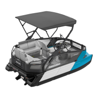
The following illustration shows which part of the
carburetor begins to function at different throttle
plate openings.
VIEW FROM AIR INTAKE OPENING
1. Throttle plate openings
2. Throttle plate closed
3. Throttle plate wide opened
4. Low-speed screw
5. Pilot jet
6. Main jet and high-speed screw
REMOVAL
To remove carburetor(s) from engine, proceed as
follows:
Remove air vent tube support (SP, SPX, GS, GSI
and GSX models).
Remove air intake silencer. Refer to FUEL SYS-
TEM 05-03.
Turn fuel valve to OFF position.
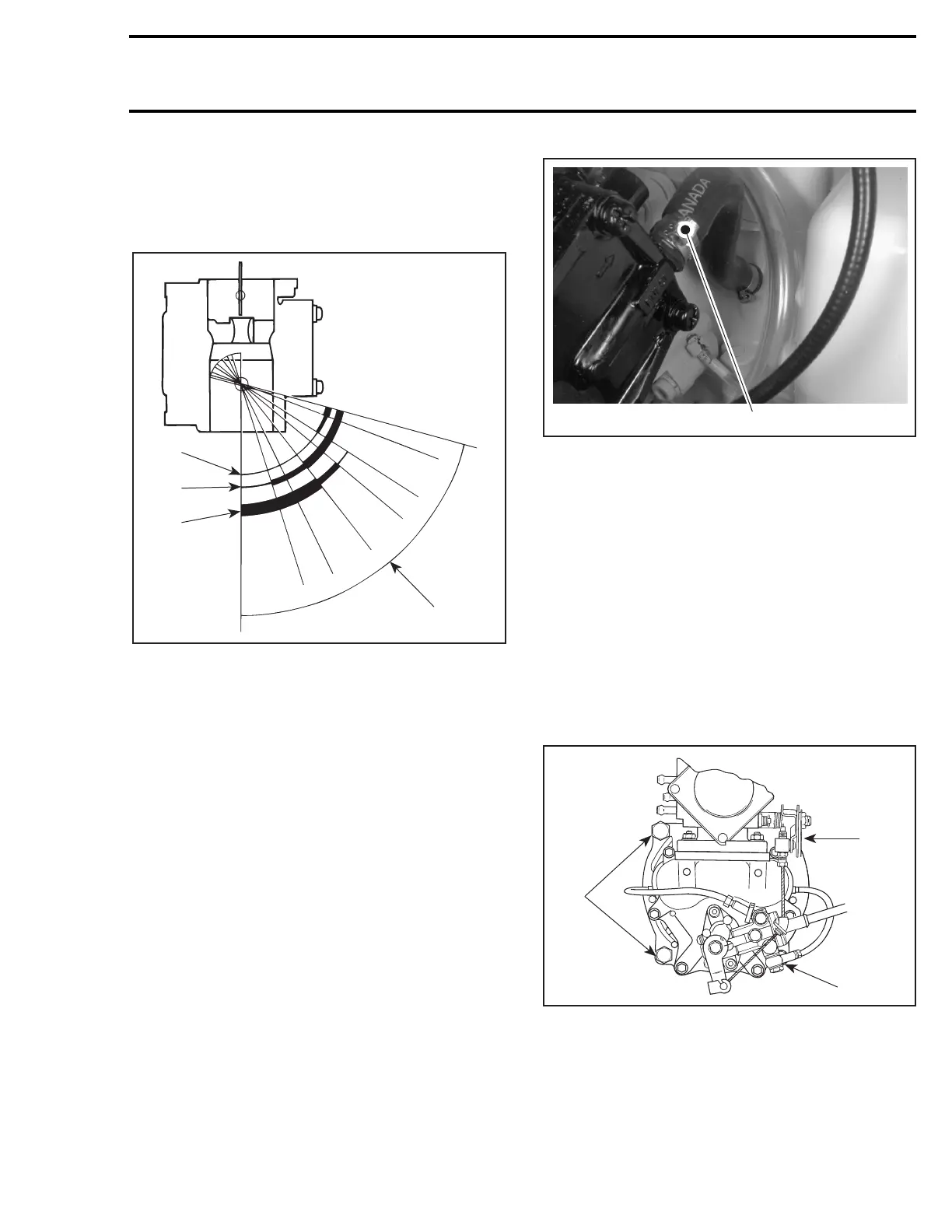
Disconnect pulse line.
TYPICAL
1. Pulse line
Disconnect fuel supply line from fuel pump.
Disconnect fuel return line.
Disconnect oil injection pump cable, throttle cable
and choke cable.
BN-38 Carburetor
Remove 4 bolts and lock washers from rotary
valve cover then move carburetors and rotary
valve on top of engine.
NOTE:
When removing rotary valve cover, pay at-
tention that the rotary valve will stay in place, oth-
erwise it must be timed.
1. Rotary valve cover bolt
Remove carburetor from intake manifold.
BN-38I and BN-40I Carburetors
Remove screws
no. 20
and lock washers
no. 21
retaining carburetors.
1
F01F13A
2
3
4
5
6
F00F05A
1
F01D4RF
1
1
1
 Loading...