Section 06 LUBRICATION SYSTEM
Sub-Section 03 (OIL INJECTION PUMP)
06-03-3
REMOVAL
717 Engines
Remove air intake silencer (refer to FUEL SYS-
TEM 05-03).
Remove rotary valve cover (refer to ENGINE 03-
07).
Remove Allen screws
no. 6
retaining intake man-
ifold
no. 4
to rotary valve cover.
Separate intake manifold from rotary valve cover.
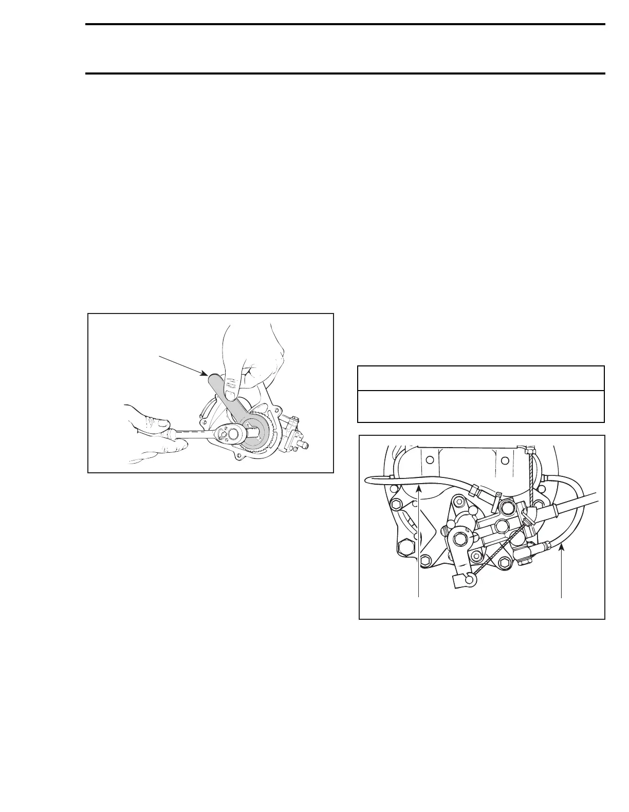
1, Oil Pump Gear
To separate oil pump from intake manifold, re-
move oil pump gear using gear holder (P/N 290
277 905) and unscrew lock nut
no. 2
.
1. Gear holder
3, Oil Injection Pump
Remove 2 Allen screws
no. 5
with flat washers
retaining oil injection pump to intake manifold.
Remove pump.
787 Engine
10, Oil Injection Pump
Disconnect oil injection pump cable
no. 7
.
Remove 2 Allen screws
no. 8
with flat washers
no. 9
retaining oil injection pump to magneto
housing cover.
Pull pump and shaft
no. 11
.
Disconnect oil hoses from fittings of oil injection
pump.
DISASSEMBLY
NOTE:
Some oil pump parts are not available in
single parts. A gasket set is available for the
pump.
If the pump is found defective, it should be re-
placed by a new one.
CLEANING
Discard all seals and O-rings. Clean metal compo-
nents in a solvent.
ASSEMBLY
717 Engines
3,4, Oil Injection Pump and Intake
Manifold
Install oil injection pump to intake manifold.
Torque screws
no. 5
to 6 N•m (53 lbf•
in
).
TYPICAL
1. Small oil line
1, Oil Pump Gear
Install gear to oil injection pump shaft. Torque lock
nut
no. 2
to 6 N•m (53 lbf•
in
).
NOTE:
Make sure one washer is installed on each
side of gear.
A00C17B
1
-
CAUTION
Whenever oil injection lines are removed, al-
ways make the routing as shown.
F01D4SA
1
1




 To Next Page