Section 03 ENGINE
Sub-Section 04 (MAGNETO SYSTEM)
03-04-3
GENERAL
The following procedures can be performed with-
out removing engine from watercraft. However,
battery removal will be required on SP and GTS
models.
REMOVAL
717 Engines
1, Magneto Housing Cover
Remove screws
no. 2
, wire supports
no. 17
and
no. 18,
then withdraw cover.
4,5, Magneto Flywheel and Ring Gear
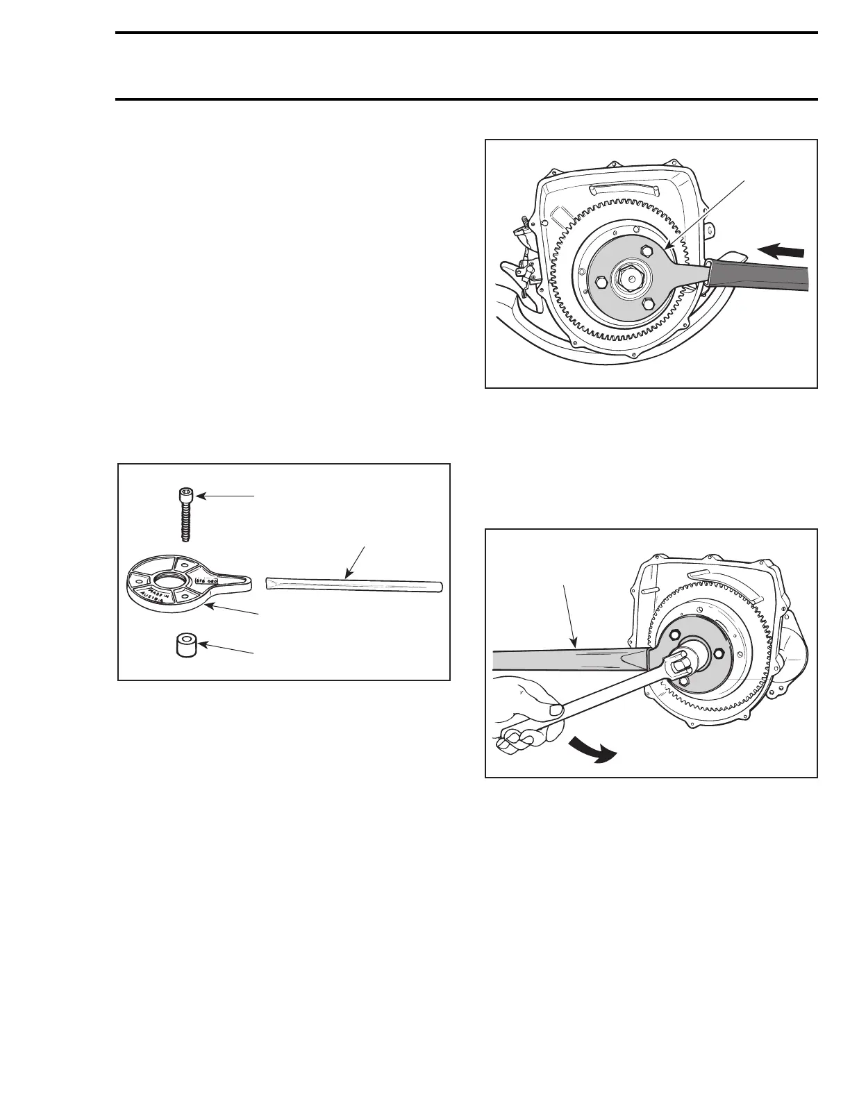
Magneto flywheel is locked with puller plate (P/N
290 876 080), sleeves (P/N 290 847 220) and ex-
tension handle (P/N 295 000 111).
1. Screw
2. Extension handle
3. Puller plate
4. Sleeve
Using 3 M8 x 35 screws (P/N 290 841 591), install
screws through puller plate and slide sleeves on
screws then secure puller plate on magneto fly-
wheel so that sleeves are against flywheel.
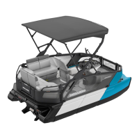
Install extension handle on end of puller plate.
TYPICAL
1. Sleeves on opposite side
Using a suitable socket, unscrew retaining nut
no. 6
COUNTERCLOCKWISE when facing it.
NOTE:
If socket is found too large to be inserted
in puller plate, machine or grind its outside diame-
ter as necessary.
TYPICAL
1. Extension handle locking crankshaft
Remove nut and lock washer from magneto fly-
wheel.
Magneto flywheel is easily freed from crankshaft
with puller (P/N 295 000 106).
F01D47A
1
2
3
4
F01D48A
1
F01D4BA
1
 Loading...