Section 08 PROPULSION SYSTEM
Sub-Section 05 (VARIABLE TRIM SYSTEM)
08-05-4
GENERAL
To test VTS control module, motor or switch, refer
to ELECTRICAL SYSTEM 07-05.
REMOVAL
Disconnect ball joint
no. 1
.
Loosen gear clamps
no. 2
.
Remove boot
no. 3
.
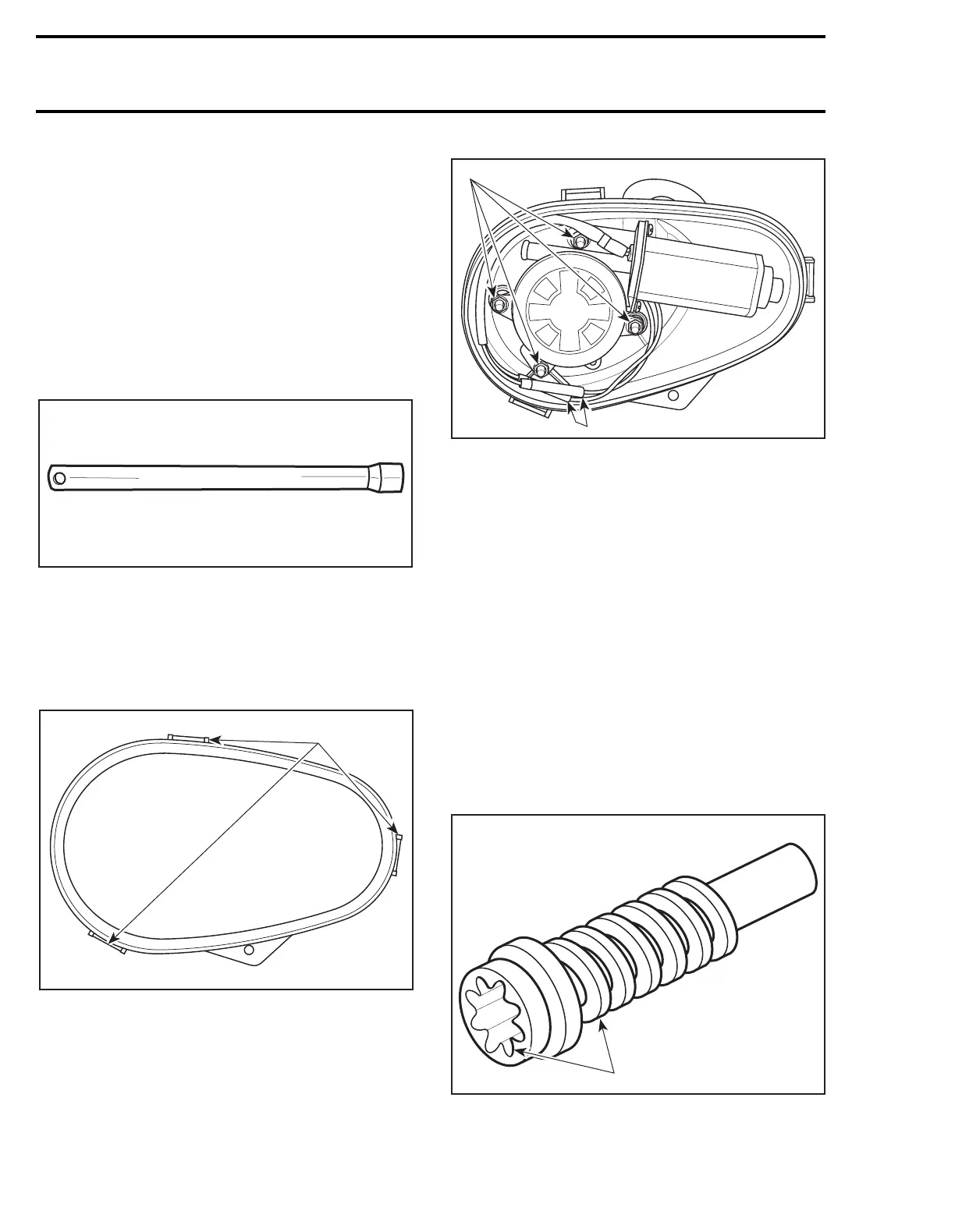
To loosen nut
no. 4
, use VTS socket tool (P/N 295
000 133).
Pull out VTS assembly
no. 6
from bilge.
DISASSEMBLY
7, Cover
Remove VTS cover by pressing on tabs.
1. Press tabs to remove cover
8, Motor
Disconnect wires of motor.
Remove retaining nuts.
1. Remove nuts
2. Disconnect wires
Pull on motor to remove it.
9,10, Worm and Sliding Shaft
Simply pull on worm and sliding shaft in order to
remove them.
INSPECTION
2, Boot
Make sure boot is in good condition. If it is
cracked or teared, replace boot.
9, Worm
Inspect threads and splines of worm for wear. If
worm replacement is necessary, renew also slid-
ing shaft.
1. Inspect threads and splines
F01B2PA
VTS
F01J1WA
1
F01J1XA
1
2
F01J25A
1
 Loading...