Section 09 STEERING SYSTEM
Sub-Section 05 (HX AND XP MODELS)
09-05-4
15,16, Steering Stem Arm and Support
Position steering stem arm and support onto
steering stem arm
no. 18
.
1. Keyways
2. Torque to 6 N•m (53 lbf•in)
3. Synthetic grease
4. Torque to 7 N•m (62 lbf•in)
5. Torque to 15 N•m (11 lbf•ft)
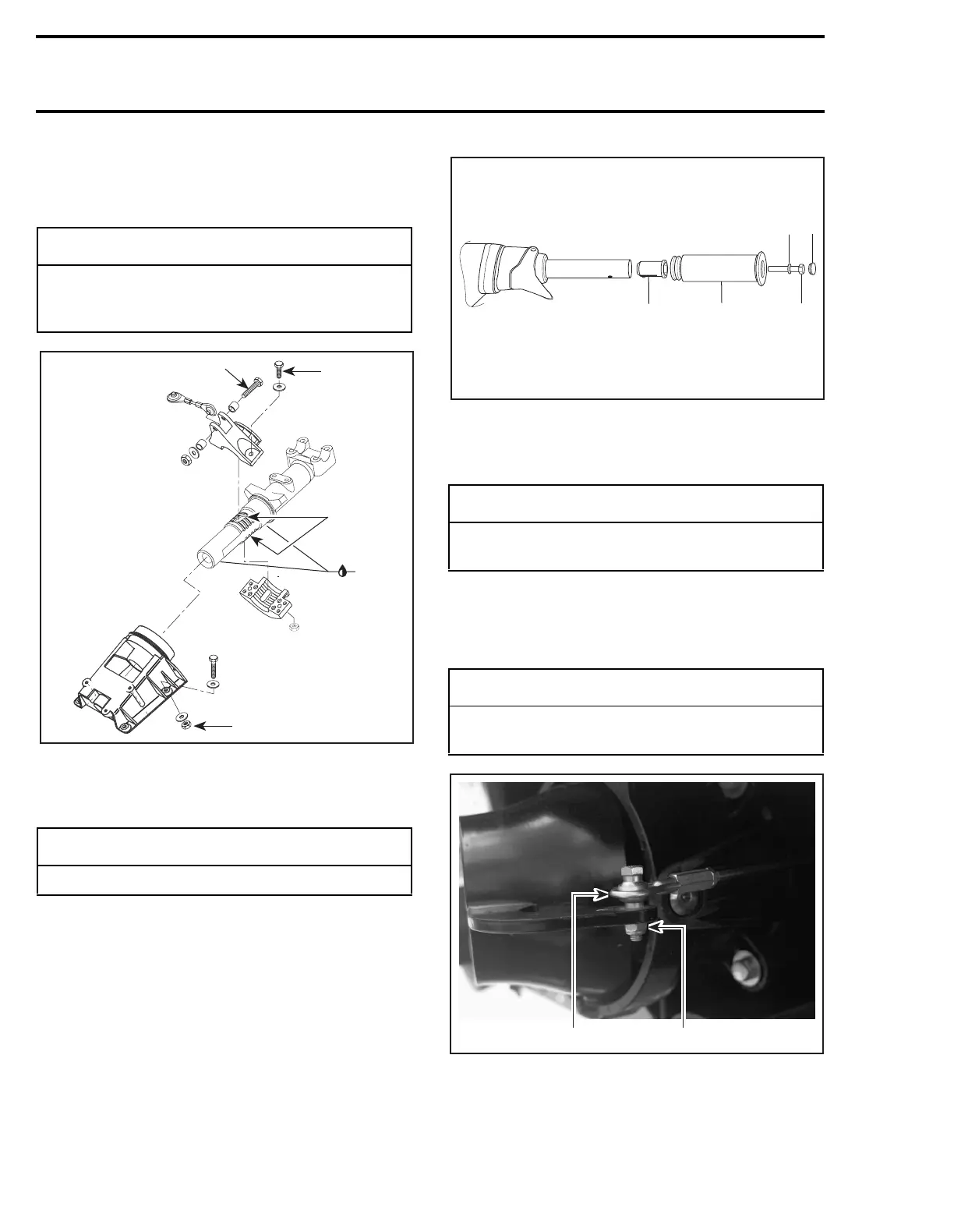
4,8, Grip and Grip Insert
When installing the grip insert in the handlebar
no. 20
, ensure that its notch is properly inserted
in the hole beneath the handlebar.
Install grip
no. 4
on handlebar
no. 20
matching it
to the hex form on the grip insert
no. 8
.
Install flat washer
no. 7
and screw
no. 6
.
Torque screw to 14 N•m (10 lbf•ft).
1. Grip insert
2. Grip
3. Flat washer
4. Screw. Torque screw to 14 N•m (10 lbf•ft)
5. Cap
23, Ball Joint
Secure the steering cable ball joint
no. 23
to the
nozzle as per following illustration.
TYPICAL
1. Ball joint on top of steering arm
2. Torque nut to 7 N•m (62 lbf•in)
◆
WARNING
Make sure integrated flat keys of steering
stem arm and support are properly seated in
steering stem keyways.
◆
WARNING
Correct torque must be strictly followed.
2
F05K08A
4
1
3
5
-
CAUTION
Ensure to install flat washer otherwise screw
will damage grip end.
-
CAUTION
Ensure the ball joint is parallel (± 5°) to the
nozzle arm.
F01K1PA
1
2
3
4
5
F06K01A
1
2
 Loading...