Section 03 ENGINE
Sub-Section 05 (TOP END)
03-05-6
All Engines
Remove tuned pipe and exhaust manifold, refer
to ENGINE 03-08.
Remove screws
no. 17
.
Remove cylinders, being careful that connecting
rods do not hit crankcase edge.
NOTE:
Even if only one cylinder needs repair,
both cylinders should be lifted to allow 1-piece cyl-
inder base gasket replacement.
3, Piston
NOTE:
The 717 and 787 engines feature cageless
piston pin bearings.
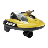
Bring piston to Top Dead Center and install rubber
pad (P/N 295 000 101) over crankcase opening. Se-
cure with screws. Lower piston until it sits on pad.
1. Rubber pad
If the other cylinder has been removed, complete-
ly cover its opening with a clean rag.
1. Openings covered with rag and rubber pad
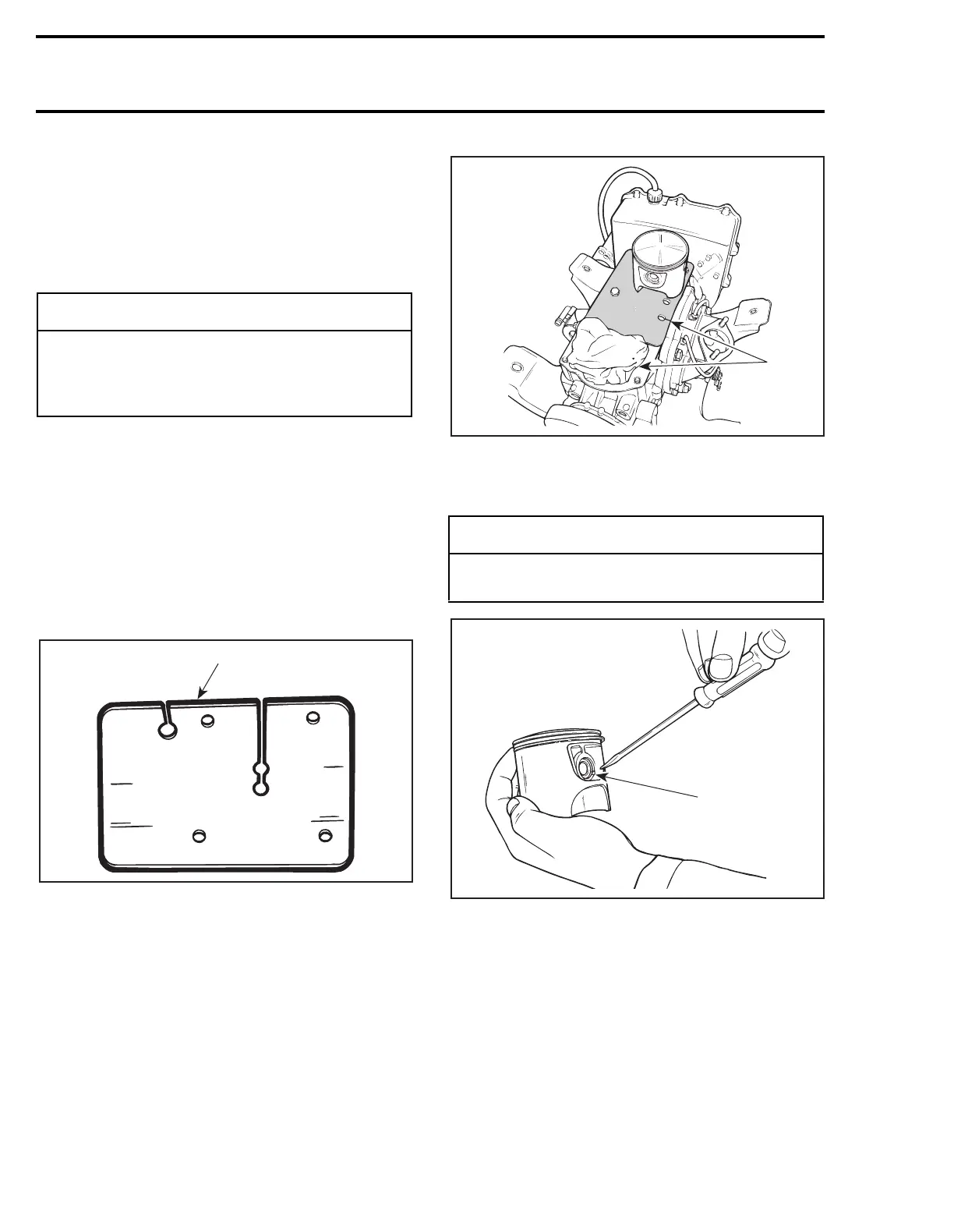
To remove circlip
no. 5
, insert a pointed tool in pis-
ton notch then pry it out and discard.
TYPICAL
1. Piston notch
To extract piston pin
no. 4
, use piston pin puller
(P/N 290 877 092) as follows:
– Fully thread on puller handle.
– Insert extractor spindle into the piston pin.
– Slide the expansion sleeve (P/N 290 877 041)
onto the spindle.
– Screw in extracting nut (P/N 290 877 155) with
the movable extracting ring towards spindle.
◆
WARNING
If screws need to be heated for removal
when engine is in watercraft, fuel system
pressurization must be done first. Do not use
open flame;
use a heat gun.
F01B0JA
1
◆
WARNING
Always wear safety glasses when removing
piston circlips.
F01D43A
1
F01D0PA
1
 Loading...