Section 03 ENGINE
Sub-Section 05 (TOP END)
03-05-10
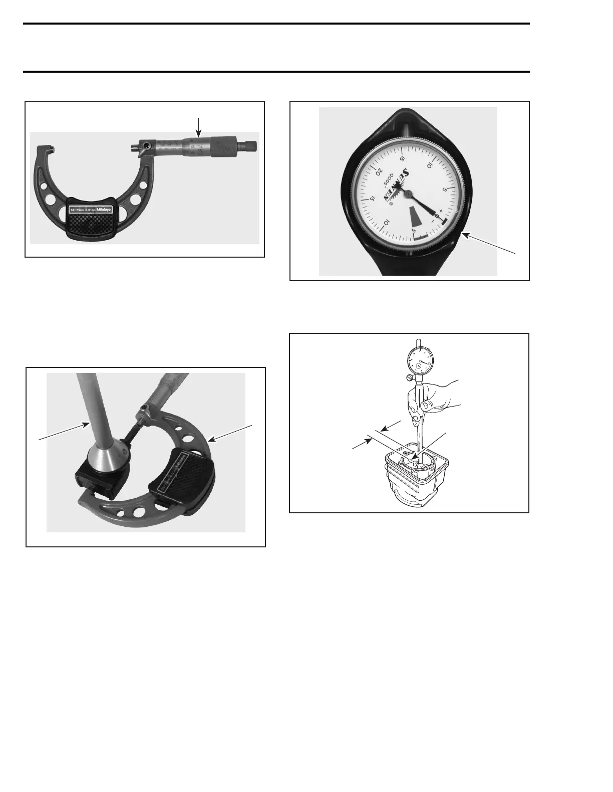
1. Micrometer set to the piston dimension
PISTON/CYLINDER WALL CLEARANCE
MEASUREMENT
Used and New Pistons
With the micrometer set to the piston dimension,
adjust a cylinder bore gauge to the micrometer di-
mension and set the indicator to zero.
1. Use the micrometer to set the cylinder bore gauge
2. Dial bore gauge
1. Indicator set to zero
Position the dial bore gauge at 16 mm (5/8 in) be-
low cylinder top edge.
1. Measuring perpendicularly (90°) to piston pin axis
A. 16 mm (5/8 in)
Read the measurement on the cylinder bore
gauge. The result is the exact piston/cylinder wall
clearance.
NOTE:
Make sure the cylinder bore gauge indica-
tor is set exactly at the same position as with the
micrometer, otherwise the reading will be false.
Ring/Piston Groove Clearance
Using a feeler gauge, check clearance between
rectangular ring and groove. If clearance exceeds
specified tolerance, replace piston.
NOTE:
Ring/piston groove clearance can be cor-
rectly measured only on rectangular ring which is
bottom ring.
F00B08A
1
F00B09A
1
2
F00B0AA
1
F01D0KA
1
A