Section 04 ENGINE (2-STROKE)
Subsection 03 (MAGNETO SYSTEM)
947 DI Engines
Stator and Trigger Coil/CPS
(Crankshaft Position Sensor)
Install the stator no. 9 and trigger no. 10 coil in
engine magneto cover. Torque screws to 9 N•m
(80 lbf•in).
Reinstall wiring harness bracket no. 29 using tap-
tite screws no. 16.
Torque trigger coil screws no. 21 to9N•m
(80 lbf•in).
Torque stator screws no. 20 to 13 N•m
(115 lbf•in).
NOTE: The trigger coil is not adjustable.
F06D0NB
1 2 3
1. Torque to 9 N•m(80lbf•in)
2. Taptite screws
3. Torque to 13 N•m(115lbf•
in)
Cover
Before installing cover, make sure oil pump shaft
is properly positioned.
Before installation, properly install O-ring no. 25 in
engine magneto cover no. 1.
Apply Loctite 767 anti-seize compound on screws
no. 11. Torque screws in a criss-cross sequence
to9N•m(80lbf•in).
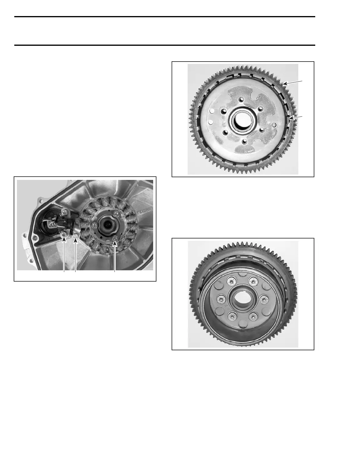
Rotor and Ring Gear
Install trigger wheel no. 30 on ring gear no. 3.
1
F18D2TA
2
1. Ring gear
2. Trigger wheel
Apply Loctite 648 (green) on mating surface of the
rotor no. 8.
Apply Loctite 648 (green) on screws no. 17 re-
taining rotor to ring gear and torque screws in a
criss-cross sequence to 13 N•m(115lbf•in).
F18D2UA
ASSEMBLED FLYWHEEL
Apply Loctite 243 (blue) on crankshaft taper.
96 smr2004-Complete Line Up
 Loading...


