HF Series Generators
Configuration
CF-1018R3
13
3. Select the first workstation to be configured, by pressing the respective
button (only the icon of the selected workstation has different color). The
console shows one of the following values:
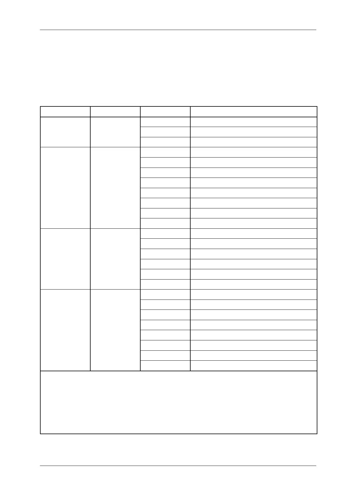
DISPLAY FUNCTION VALUE DESCRIPTION
0 No-configured workstation
1
st
Value TUBES
1 Tube-1
2 Tube-2
0--Direct Direct (No Bucky)
1 -- Bucky 1 Bucky-1
2 -- Bucky 2 Bucky-2
DE
ICES --
3--STDTomo Standard Tomo
*1)
2
nd
alue
WORKING MODE
4--STDRF Standard RF (Spot Film Device)
5--DSI Digital RAD and Fluoro
*2)
6--Cine Cine
*2)
7--DSA DSA
*2)
0 No AEC
1 Ion Chamber-1 (IC-1)
ION
2 Ion Chamber-2 (IC-2)
3
rd
alue
CHAMBERS
3 Ion Chamber-3 (IC-3)
4 Ion Chamber-4 (IC-4)
5 Photomultiplier (PT-INPUT)
1 Formula-1
2 Formula-2
3 Formula-3
k
TR
C
ING
4 Formula-4
4
th
alue
(OPTIONAL)
5 Formula-5
6 Formula-6
7 Formula-7
8 Formula-8
Notes:
-- Some of listed values are not configurable depending on the Generator model .
*1) Only when the Tomo is controlled from the Generator. In this case, the workstation has to be configured as Tube “1” or “2”,
Device “STD Tomo” and Ion Chamber “0”.
If the Tomo is controlled from the Table, the workstation has to be configured as Tube “2”, Device “STD RF” and Ion Chamber “0”.
*2) These Devices are only available for Generators provide with interface option for Digital Systems. These workstations has to
be configured as Tube “2”.