HF Series Generators
Calibration
CA-1036R2
50
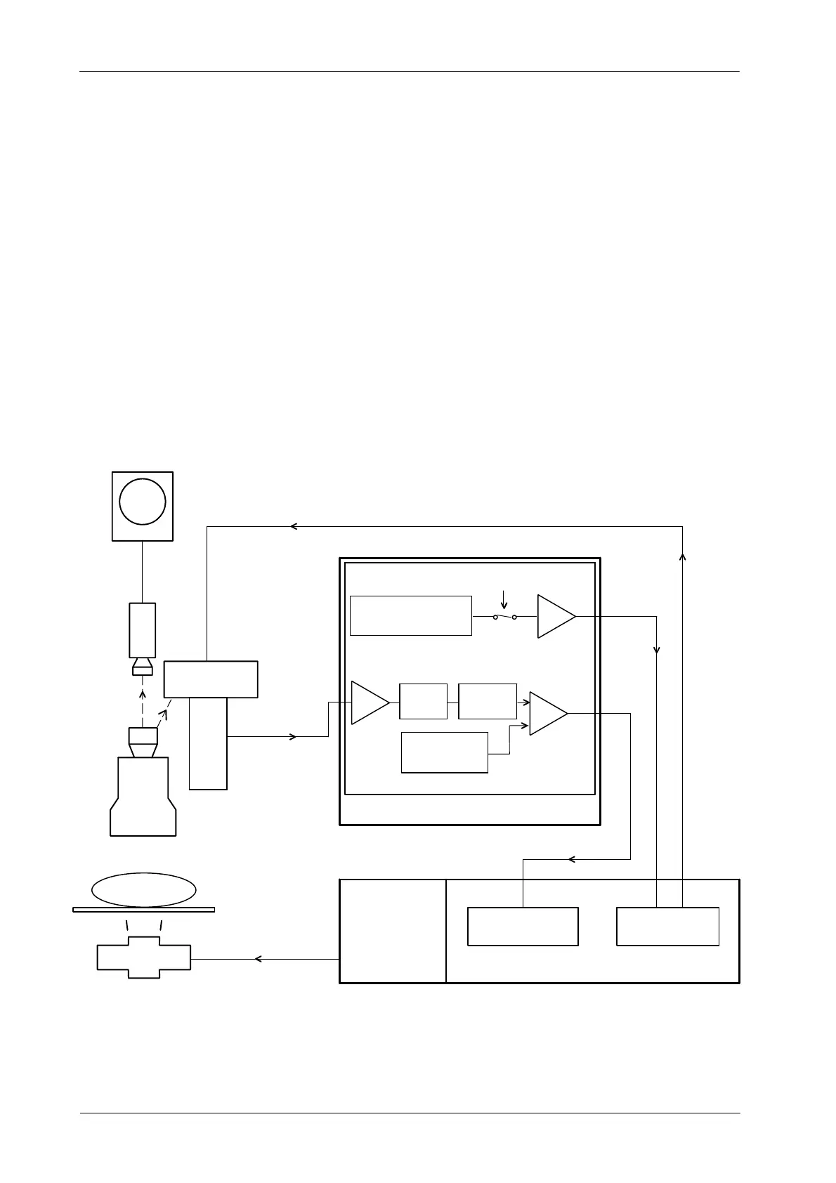
The optimum brightness level in ABC mode is set by adjusting Brightness
Control Resistor R13 on the AEC Control Board, which controls the output of
the Photomultiplier Tube High Voltage power supply on the Interface Control
Board ( “PT CRL” plus 5 volts programs the output to be 0 volts, and 0 volts
programs the output to approximately --1200 volts). The window comparator
requires an input range from 0 to +10 VDC for the “ABC IN” (the optimum
brightness level will be achieved with a value between 5 and 7 VDC).
Illustration 2-5
ABC System for Photomultiplier Tube
I/V
CONVERTER
U10
SAMPLE
&
HOLD
WINDOW ADJ.
R11 -- R14
BRIGHT. LEVEL ADJ.
R13
FL
U2
U8
U12
MONITOR
VIDEOLIGHT
TV
CAMERA
IMAGE
TUBE
PHOTOMULTIPLIER
PT INPUT
(Brightness signal)
PT SPLY
(Photomultiplier Voltage supply)
PATIENT
X-RAY TABLE
X-RAY TUBE
CONTROL CONSOLE
AEC CONTROL PCB
WINDOW
COMPARATOR
BUFFER
POWER MODULE
INTERFACE
CONTROL PCB
HT CONTROL PCBHV
TRANSFORMER
PT CRL
KVUP&KVDWN
PEAK
DETECT.
PHOTOMULTIPLIER
AMPLIFIER
BOARD (A3168--xx)