HF Series Generators
Calibration
CA-1036R2
51
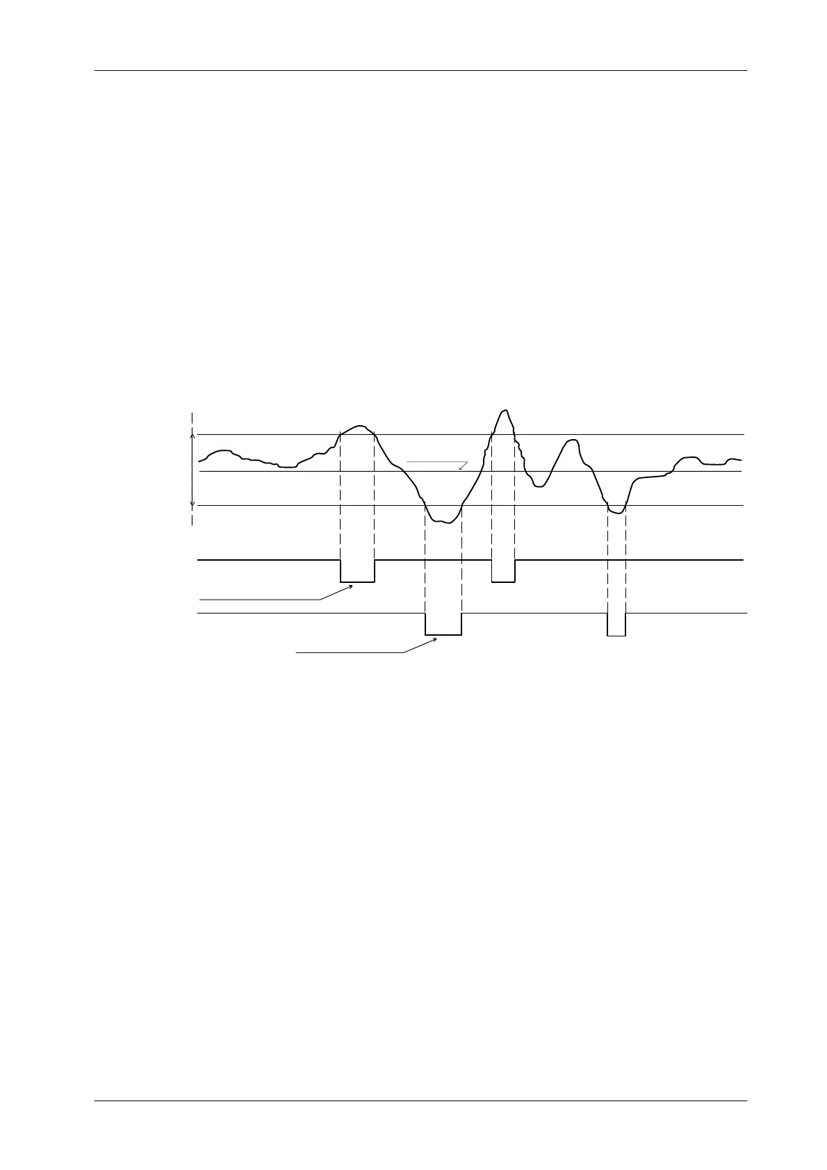
Window reference could be adjusted first to set mid-way the brightness level
(+5 VDC), and second to increase or decrease the range of response and
sensitivity of the kV control to input variations (brightness changes). If oscillation
occurs during ABC fluoro exposure, increase the dead zone by adjusting
Resistors R11 and R14 on the AEC Control Board. (Refer to Illustration 2 -6 for
ABC waveforms).
Illustration 2-6
ABC Waveforms in AEC Control Board
Command to drive
thefluorokVpUP
High Logic
Low
Logic
Command to drive
thefluorokVpDOWN
UP PT reference (R14)
DWN PT reference (R11)
Brightness level
(Gain adj.)
ABC IN
(U8--8)
--kV Down (J1--19)
-- k V U P ( J 1 -- 6 )
window reference
Adjust the ABC system for Photomultiplier Tube as follow:
1. Be sure that the Video System and the Image Intensifier are powered and
operating correctly.
2. Set up a Dosimeter as close as possible to the Image Intensifier
Radiation Input to measure the Entrance Image Intensifier Exposure
Dose Rate. Position the Probe at the center of the primary beam with the
entire active volume w ithin the primary beam.
Place the Tube-Collimator Assembly at the normal SID (1 meter), fully
open the Collimator Blades and align the Image Intensifier with the light
beam.