HF Series Generators
Installation
IN-1052R0
6
6. Previous to install the Generator Cabinet on the upper side of the
Positioner Control Box, it is recommended to perform the Power Line
connection.
KEEP IN MIND THE GENERAL CAUTIONS FOR LINE
POWERED GENERATORS INDICATED IN SECTION 1.3.
DO NOT POWER ON THE GENERATOR UNTIL SPECIFICALLY
INSTRUCTED IN THIS SERVICE MANUAL.
7. The power supply line should conform with the Generator model defined
in the “Pre-Installation” document. Wire sizes indicated in this document
are relative to the power supply line and wire length. Verify that the power
line voltage and phase of the Generator coincides with the one for Room
Electrical Cabinet.
As indicated in the Pre-Installation document, 16 mm
2
(AWG 6)
may be used from the Room Electrical Cabinet to the Generator
Cabinet provided that the length does not exceed 6 m (20 ft).
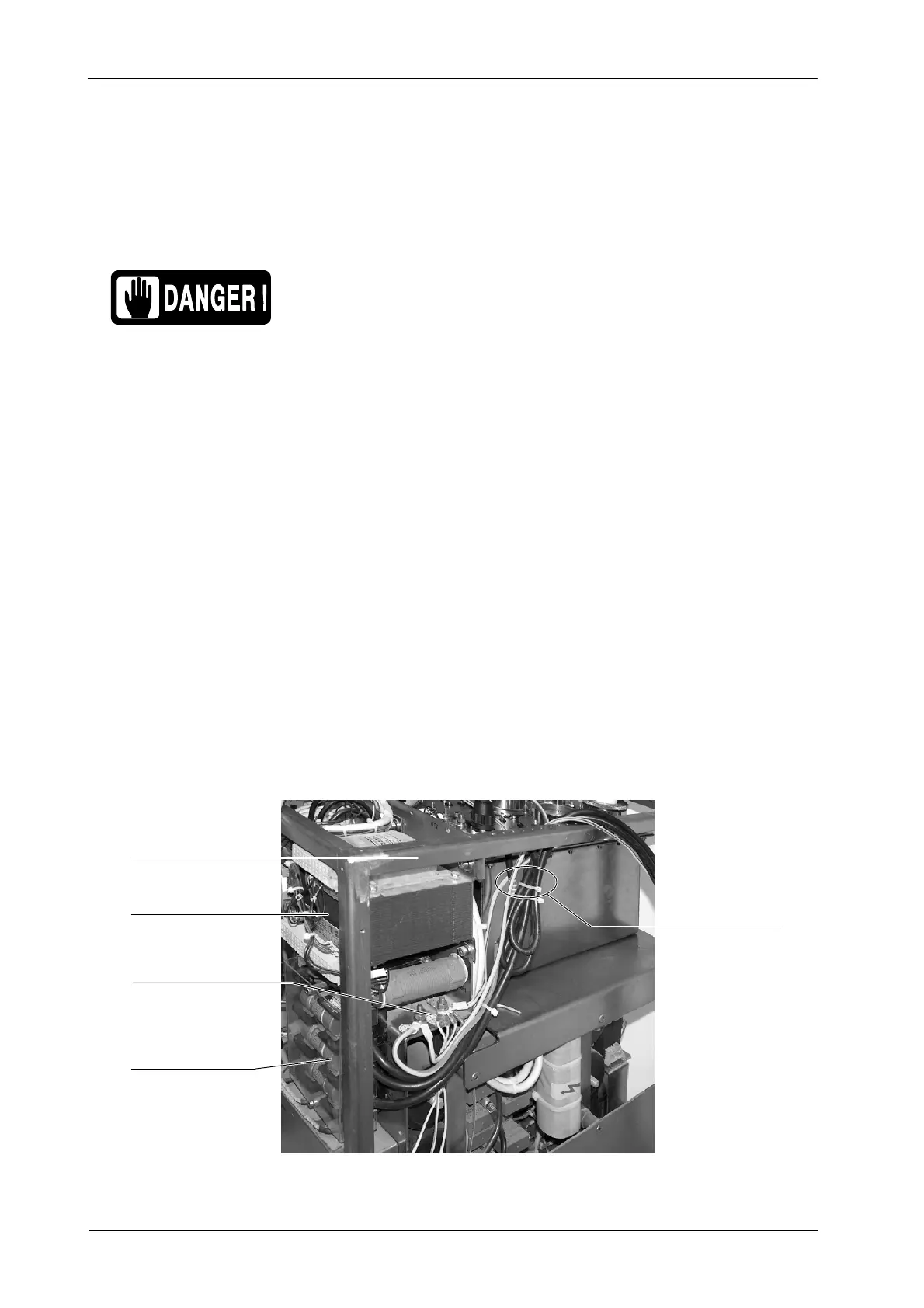
8. Route the Power Line Cables and the Ground wires to the Input Line
Fuses and Ground Studs in the Cabinet Frame (Ground Studs are above
the input fuses or close to the right side of the HV Transformer). These
cables can be secured to the Fastening Bar of the Cabinet and routed
internally along the r ear side of the Cabinet (always apply Local Codes
for cable routing). (Refer to Illustration 2-2.)
Illustration 2-2
Cable Routing in the Line Powered Generator
Power Line Cables
Input Line Fuses
Fastening Bar
Ground Terminals
Input Transformer 6T2
Note .