HF Series Generators
Installation
IN-1052R0
20
FANS
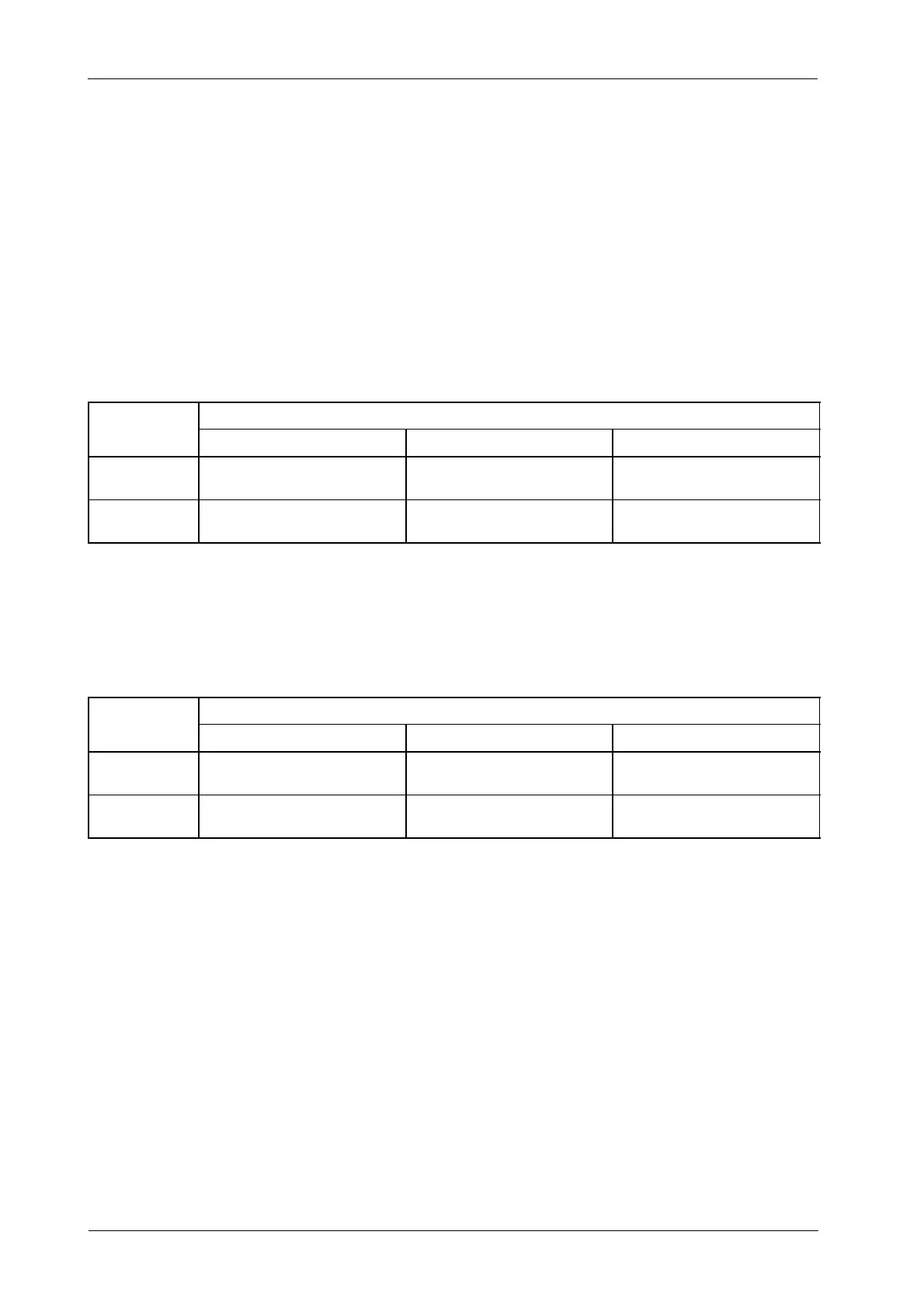
Wires from fans should be routed with the Stator Cables, and connected to the
indicated terminal of the Generator Cabinet. Depending on the model of X-ray
Tube, the fans are powered at 115 VAC or 220 VAC. Make the following
connections to select the fan voltage.
For Compact Generators with the Low Speed Starter LF-RAC located on a shelf
at the bottom of the Generator (module-10), connect wires from fans to:
TUBE
GENERATOR WITH LOW SPEED STARTER
CONNECTION
WIRES FROM FANS 115 VAC 220 VAC
AS TUBE-1
10TS2-6 and 10TS2-7
on the Generator Cabinet
TB4-T1 with TB1-22 or TB1-23
on the LF-RAC Board
TB4-T1 with TB1-25 or TB1-26
on the LF-RAC Board
AS TUBE-2
10TS2-14 and 10TS2-15
on the Generator Cabinet
TB4-T2 with TB1-22 or TB1-23
on the LF-RAC Board
TB4-T2 with TB1-25 or TB1-26
on the LF-RAC Board
For Compact Generators with the High Speed Starter LV-DRAC located on a
shelf at the bottom of the Generator (module-11), connect wires from fans to:
TUBE
GENERATOR WITH HIGH SPEED STARTER
CONNECTION
WIRES TO FANS 115 VAC 220 VAC
AS TUBE-1
11TS2-6 and 11TS2-7
on the LV-DRAC Module
wire marked “T1” with 11TS2-17
on the LV-DRAC Module
wire marked “T1” with 11TS2-18
on the LV-DRAC Module
AS TUBE-2
11TS2-14 and 11TS2-15
on the LV-DRAC Module
wire marked “T2” with 11TS2-17
on the LV-DRAC Module
wire marked “T2” with 11TS2-18
on the LV-DRAC Module