HF Series Generators
Installation
IN-1052R0
21
THERMOSTAT OR PRESSURE SWITCH SIGNAL
If the X-ray Tube is provided with a Safety Thermostat (approx. 65
o
C) or
Pressure Switch (must be NC Contact), the two wires should be routed to the
Terminal Block TS2 in the Generator Cabinet and connected to the following
Terminals.
In case that the X-ray Tube is provided with a Safety Thermostat (approx. 65
o
C)
and a Pressure Switch (both must be NC Contacts), connect them in series
before routing, connecting both wire-ends to their respective Terminals in TS2.
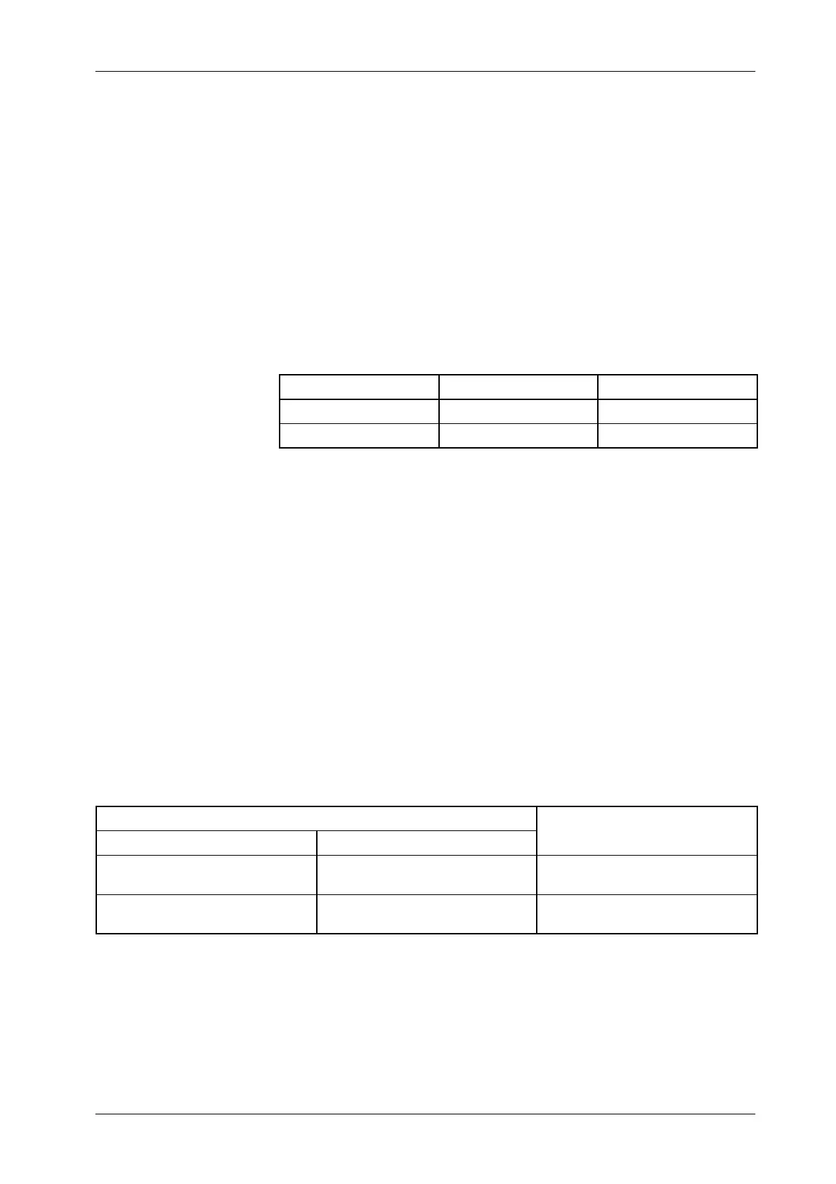
THERMOSTAT WIRES TUBE-1 TUBE-2
THERMOSTAT SIGNAL TS2-4 TS2-12
THERMOSTAT COMMON TS2-5 TS2-13
Terminal Block TS2 may be marked as 10TS2 or 11TS2
depending on the Generator model.
If an X-ray Tube is not provided with Thermostat signal, jump both connections
in the Terminal Block TS2 (refer to above table).
GND AND/OR SHIELD
The connection of the GND and/or Shield wire of the Stator c ables depend on
the Generator model.
GENERATOR MODEL
CONNECTION OF
Number of X-ray Tubes Starter type and Location
GND and/or SHIELD WIRE
1 or 2 Tubes
LF-RAC (Low Speed)
Lower Cabinet Shelf (Module 10)
10TS2--8 or 10TS2--16
1 or 2 Tubes
LV-DRAC (High Speed)
Lower Cabinet Shelf (Module 11)
11TS2--8 (for Tube-1)
11TS2--16 (for Tube-2)
Note .