HF Series Generators
Installation
IN-1052R0
29
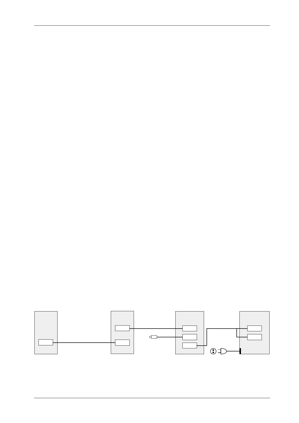
VIRTUAL CONSOLE ( PC) USING A POSITIONER WITH TOUCH SCREEN
Systems using a Virtual Console running on a PC usually must have a PC
Interface Box installed between the PC and Generator.
(Refer to Illustration 3-5)
Perform the following connections:
1. Remove the Back Cover of the PC Interface Box.
2. Connect the Serial Interconnection Cable (A3352--01) from J1 of the PC
Interface Box to J2 “Console” of the System Interface Panel in the Control
Box.
3. Connect the Serial Interconnection Cable (A7067--xx) from J1
“Generator” of the System Interface Panel in the Control Box to J5 of the
Generator Cabinet.
4. Connect the Handswitch Cable to J2 of the PC Interface Box.
5. Connect the Interface Box--Computer Cable (A3363--01) to J3 of the PC
Interface Box and the other end (2 connectors) to COM1
(Communication) and J1 (Auto ON/OFF) of the Computer connectors.
J1 connector is only available in Computers provided with Auto
ON/OFF Board inside (factory installed).
6. Re-install the Back Cover of the PC Interface Box.
7. Check to set proper Line Voltage on PC. Plug the Power Line cable for
the Computer to a 110 VAC or 230 VAC socket.
For further information, refer to Section 5.2 -- Maps 54301052,
A6188--03 and I/F-036, and refer to the respective Positioner
Service Manual.
Illustration 3-6
Connection of the Virtual Console (PC) using a Positioner with Touch Screen
J2
CONTROL
BOX
J1
J2
PC INTERFACE
J3
BOX
J1
COM1
PC (COMPUTER)GENERATOR
CABINET
SERIAL CABLE (A3352--01)
HANDSWITCH
PC BOX / PC CABLE
(A3363--01)
POWER LINE CABLE
TO 110
230 V
C SOCKET
J5
J1
SERIAL CABLE (A7067--xx)
Note .
Note .