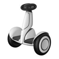
Segway®PersonalTransporteri2,x2,x2Turf PartsReplacementGuide 9‐13
6. LiftEMIfilterofflocatorpinanddisconnect
(2)balancesensorassemblyharness
connectorsfrombottomofEMIfilterby
holdingdownlockingtabonconnector.See
Figure9‐15.
Figure9‐15:DisconnectorConnectBalanceSensor
AssemblyHarnessConnectors
7. UnseatBSAharnessesfromplastic
positioningclips.
8. Setas
ideEMIfilterandplaceinESDbagor
oncleanESDworksurface.
To install EMI Filter:
1. MakesureSegwayPTispoweredoffand
unplugged.
2. An
yPTwithoutferritecoresmustbe
retrofittedwithferritesuponreassembly.
Onesmallferritecore(21270‐00001)is
placedoneachBSAharnessbetweenchassis
coverandEMIfilter.Onelargeferritecore
(21271‐00001)isplacedonBsideCU
hardness(10‐pinconnector)betweenchassis
coverandUIC.
Ferrite cores can physically impede installation of
new UIC. Take special care to correctly place
ferrite cores and route cables to avoid damage or
pinching when installing UIC.
3. PositionEMIfilterandconnect(2)balance
sensorassemblyharnessconnectors.See
Figure9‐15.
4. Se
atEMIfilterinplaceoverlocatorpin.
Thread(1)SHCS,M6
x1x30,SEMS,6‐lobe
fastener(20539‐00001)throughEMIfilter
andbaseplateintochassiscover.
SeeFigure9‐14.
5. Rou
teandconnect(2)steeringsensor
harnessesaroundbossesasshownin
Figure9‐13.Pr
operroutingensurescables
willnotbepinche
dwhenyouinstallconsole
cover.Reinstallretentionputtytohold
harnessesinplace.
6. Usin
gT‐306‐lobewrench,driveeachscrew
andtorqueto11.0N‐m.
7. Pe
rformpost‐servicetests(pageA‐1).
 Loading...