6-18
Installation Conditions and Method
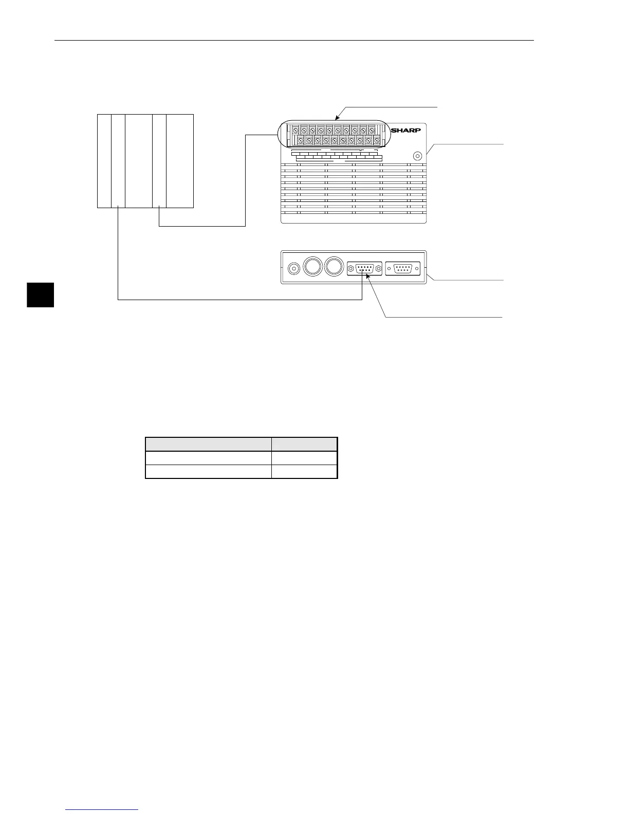
6
[6] Connecting a programmable controller using the computer link function
Connect a programmable controller to the communication connector (RS232C/RS422) and the input/
output terminals on the IV-S20 main housing.
1Connect the computer link connector (RS-232C/RS-411) of a programmable controller to the
communication connector (RS232C/RS422: 9-pin D-sub, female) on the IV-S20 main housing.
- See Chapter 14 "Computer Link" for details about the procedure for connecting to specific
manufacturers' controllers.
(The pin arrangement of the communication connector on the IV-S20 main housing is
shown on page 6-16 to 6-17.)
- In the case of RS-232C, the maximum communication cable length depends on the com-
munication speed.
Y0 Y1 Y2 Y3 Y4 Y5 Y6 Y7 BUSY C(-)
X0 X1 X2 X3 X4 X5 X6 C(+) +24V 0V
IV-S20
VIDEO CAMERA1 CAMERA2 RS232C/RS422 REMOTE
POWER
OUTPUT
INPUT POWER
▼ ▼
(side view)
Communication connector
(RS232C/RS422)
RS-232C/RS-422
Input/output terminals
1
2
(plan view)
Communication port
O/I
Programmable controller
IV-S20 main
housing
IV-S20 main
housing
2Connect the input/output terminals of the programmable controller to the input/output terminals
on the IV-S20 main housing.
- See item [4] "Connecting to the input/output terminals (parallel I/F)" for details about wiring
procedure.
9.6, 19.2
38.4, 57.6, 115.2
15 m or less
2 to 3 m
Communication speed Cable length
Conduct a communication test before using the devices for measurements.