6-16
Installation Conditions and Method
6
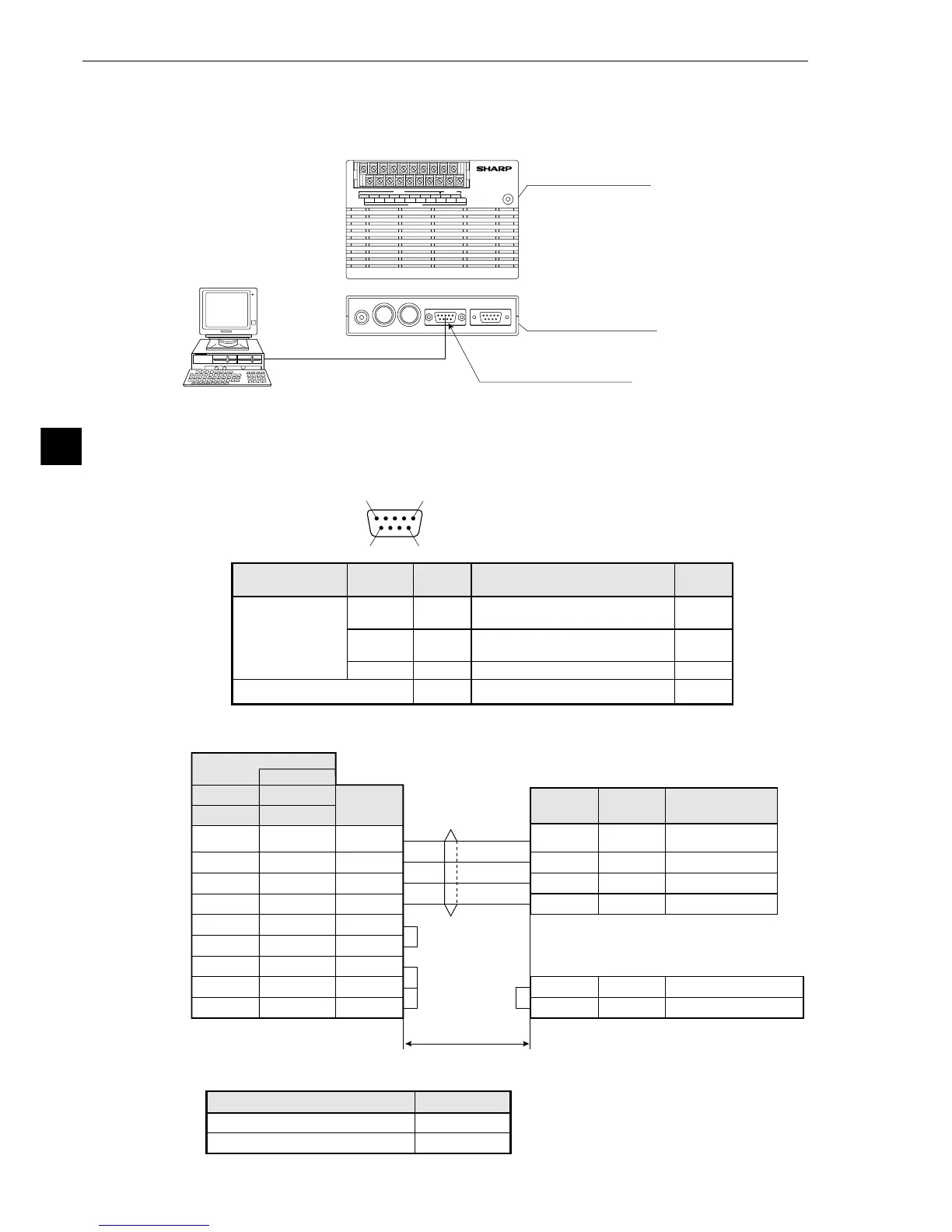
[5] Connection for communications with personal computer (general purpose serial I/F)
Connect a personal computer to the communication connector (RS232C/RS422) on the IV-S20 main
housing.
A 9-pin D-sub, male connector is included with the IV-S20, IV-S20N, and IV-S20M.
Y0 Y1 Y2 Y3 Y4 Y5 Y6 Y7 BUSY C(-)
X0 X1 X2 X3 X4 X5 X6 C(+) +24V 0V
Personal
computer
IV-S20
VIDEO CAMERA1 CAMERA2 RS232C/RS422 REMOTE
POWER
OUTPUT
INPUT POWER
▼ ▼
Communication connector
(RS232C/RS422 : 9-pin D-sub female,
rock screw M2.6)
RS-232C/RS-422
IV-S20 main housing
(side view)
IV-S20 main housing
(plan view)
- IV-S20 pin arrangement of the communication connector (for RS-232C)
51
96
(9-pin D-sub, female)
Communication
standard
Signal
name
Pin No. Details
Direc-
tion
RS-232C
Connector shield
2
3
5
RD
SD
SG
Transmitted data
(IV-S20-personal computer)
Input
Output
Frame ground
−
−
Signal ground
Received data
(personal computer-IV-S20)
FG
(1) When communicating through the RS-232C port
1
6
FL1
FL2
Memory protection 1
Memory protection 1
Communication connector on the IV-S20
(RS232C/RS422: 9-pin D-sub)
2
3
5
RD
SD
SG
Received data
Transmitted data
Signal ground
Function
3
2
5
7
8
6
1
4
Pin No. Pin No.
Pin No.
DOS/V, IBM-PC
SD
RD
SG
RS
CS
DSR
CD
DTR
Signal
name
Signal
name
PC98 series
2
3
7
4
5
6
8
20
*(RS-232C)
Personal computer
Connector
case
Connector
case
Connector
case
9-pin D-sub 25-pin D-sub
FG FG
Frame ground
*The maximum length of the communication cable depends on the communication speed.
9.6,19.2
38.4,57.6,115.2
15 m or less
2 to 3 m
Communication speed (kbps) Cable length
· Conduct a communication
test before using the devices for
measurements.