8-9
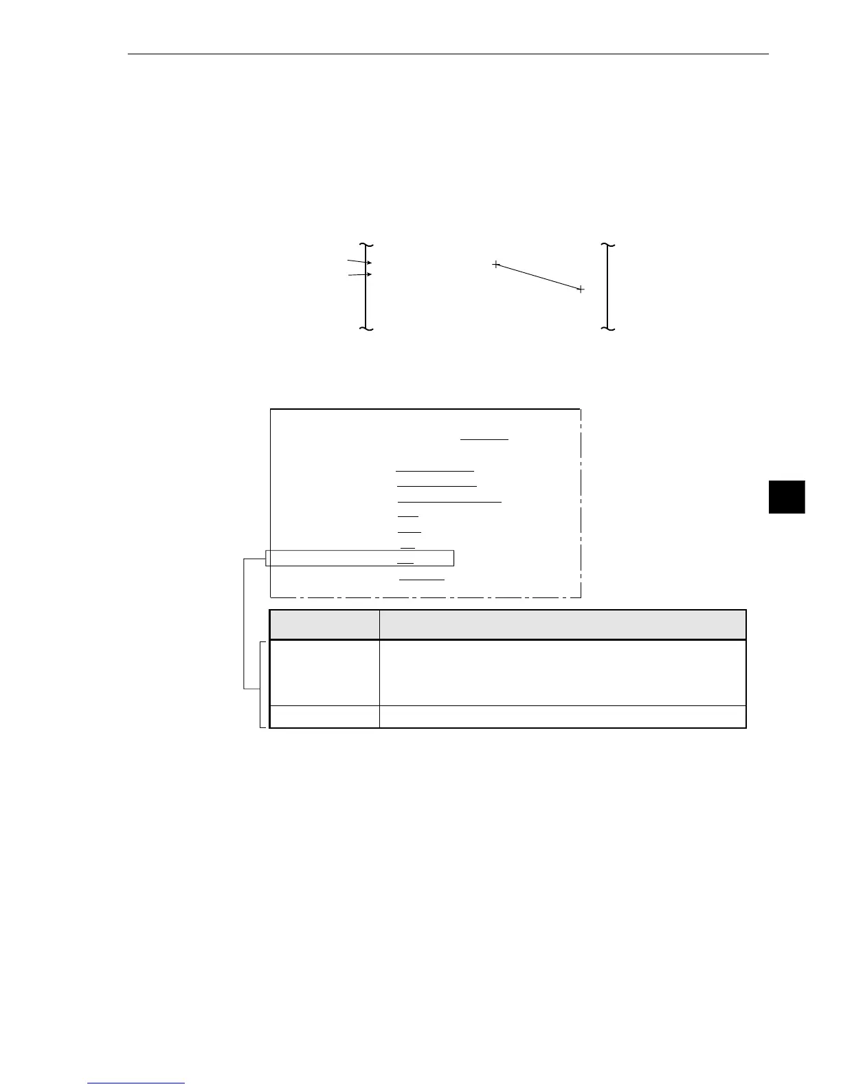
Run Menu Conditions and Settings
8
The type can be manually changed on the MAIN OPS MENU.
Note: If OBJ. NO. MANL MODE is set to YES, the type cannot
be changed with an external interface (parallel I/O or
general purpose serial IF).
YES
NO The type cannot be manually changed on the MAIN OPS MENU.
Description
[RUN MENU SETTINGS]
9
OBJ. NO.
MANL MODE
1MONITOR OUTPUT CAM1 CAM2 CAM1&2
2CAMERA1&2
CAM1=MD CAM2=MD
3CAPTURE AN IMAGE PARTIAL-IMAGE WHOLE-IMAGE NO
4MESSAGE DISPLAY
YES(RESULT.OK) YES(RESULT.NO) NO
5PATTERN DISPLAY MEAS-RESULT- OUT NO
6SHOW BINARY IMAGE
YES NO
7SHOWCORRECTIMG
YES NO
8DISPLAY + CURSOR
NO YES MANL-MESR
9OBJ.NO.MANL MODE
NO YES
0IMAGE DISPLAY FREEZE THROUGH
qUPPER MENU
[Operation procedure]
1. On the [RUN MENU SETTINGS] menu, move the cursor to item 9 OBJ. NO. MANL MODE with the
up and down keys, and press the SET key.
2. Move the cursor to YES or NO with the left and right keys, and press the SET key.
[Changing the object type on the MAIN OPS MENU]
1. Move the cursor to MANL-TYPE-CHG with the left and right keys.
2. Change the object type number (displayed in the uppermost area) with the up and down keys.
[8] Manually setting the object type
On the [MAIN OPS MENU], the object type (00 to 15) can be changed manually (using the remote key
pad).
3. Select NO.0 CHG using the left and right keys
- When NO.0 CHG is selected, you can move designated point 0. (When you select NO.1 CHG,
you can move designated point 1.
4. Move designated point 0 using the up/down and left/right keys. When it reaches the desired
position, press SEL to confirm the position.
5. Designate point 1 by repeating steps 2 to 4 above.
-Now the distance between designated points 0 and 1, designated manually above, and X
coordinate distance, and Y coordinate distance can be displayed.
[[MANL-MESR]
DTC. CORD0 (192, 191)
DTC. CORD1 (410, 256)
DIST-BETWE 227. 4
DIST-BETW-X 218. 0
DIST-BETW-Y 000. 0
Coordinates of
designate point 0
Coordinates of
designate point 1