7-12
7
Setting and Operating Outlines
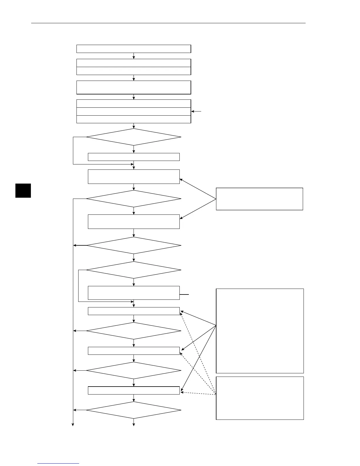
[2] Operation flow after a measurement start input signal is given
Yes
No
No
No
No
No
Yes
No
Yes
Yes
Yes
No
Yes
Yes
(*)
The window coordinates are
corrected within the range set for
each type of measurement,
based on the correction value
determined in the steps marked
with an (*)
Start (measurement start input ON)
Illuminance monitor set
External interface inhibit
(key, communications, parallel)
PC calculation
Parallel output (Y0 to Y15), "BUSY" ON
Executing illuminance monitoring
An error was detected
An error was detected
An error was detected
An error was detected
An error was detected
Executing measurement 1
Executing measurement 2
Executing measurement 3
Setting the coordinate correction
value (X, Y, θ)
① (To the next page)② (To the next page)
Positional correction
Executing measurement 0 using
camera 2
Executing measurement 0 using
camera 1
Measurement timer start
Reading the object type No.
Image capturing (camera 1/2)
The range of the lines to be captured,
as set in the measurement conditions,
is fetched.
[Measurement program to be
selected]
· Positional diviation measurement
[Measurement programs to select]
· Matching inspection for shape
and size
· Distance and angle measurement
· Lead inspection
· Area measurement after binary
conversion
· Counting by quantities by binary
conversion
· Label measurement by binary
conversion
· Detect existence using point
measurements