10-3
PC Function
10
10-2 Ladder circuit program creation
[1] Procedure for creating measurement output condition and a ladder circuit
A separate ladder circuit can be created for positional deviation measurement, degree of match
inspection, distance/angle measurement, lead inspection, area measurement by binary
conversion, object counting by binary conversion, label measurement by binary conversion, and
point measurement.
The procedure for creating a ladder circuit for positional deviation measurement is given below. A
ladder circuit can be created the same way for other measurement just change the input contact
point setting.
(1) Operation to invoke the [OUTPUT CONDITIONS] menu (for positional deviation measurement)
1. Move the cursor to item 1 SELECT MEAS. TYPE with the up and down keys, and press the
SET key. Then, move the cursor to MEAS-POSITION DEVIATE. with the left and right keys, and
press the SET key.
2. Move the cursor to item 7 OUTPUT CONDITIONS with the up and down keys, and press the
SET key. - The [OUTPUT CONDITIONS] menu will be displayed.
3. After moving the cursor to item 1 PAGE NO. with the up and down keys and after pressing the
SET key, specify page number 0 with the up and down keys. Set the REG. item to YES with the
left and right keys, and press the SET key. - Items 2 to 5 will be displayed.
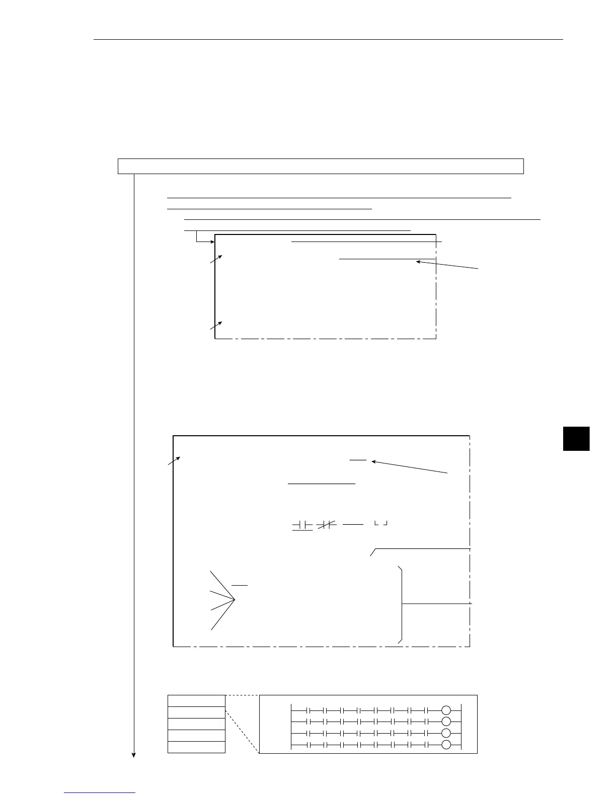
A ladder circuit program can be created on each page from 0 to 4 consisting of 4 rows, each of
which has 8 terminals and 1 output relay. Therefore, a ladder circuit can be created that
consists of 20 rows in all (one row contains 8 terminals and 1 output relay). Calculations will be
carried out in the order of the page numbers 0, 1, 2, 3 and 4.
10 234567
Output
Input 0
Input 1
Input 2
Input 3
Page 0
Page 1
Page 2
Page 3
Page 4
Continued on the following page
Displayed when
the object type 00
has been specified
On the MAIN OPS MENU, move the cursor to SET-SCRN item, and press the SET key.
-On the [SYSTEM SETUP] menu, move the cursor to item 2OBJECT TYPE COND
(condition of object type), and press the SET key.
-On the [OBJECT TYPE COND] menu, move the cursor to item 4 MEAS.0 CAMERA1,
or item 6 MEAS.0 CAMERA2, and press the SET key.
[TYPE00-MEAS0]
1SELECT MEAS. TYPE NO MEAS-POSITION-DEVIATE
2COPY :
EXEC←TYPE00−CMR1DIFF.MESURE.
3INITIALIZATION
EXEC
4MEAS. PROG. COND (TO NEXT SUB-MENU)
5EVALUATION COND (TO NEXT SUB-MENU)
6NUMERIC CALC COND
(TO NEXT SUB-MENU)
7OUTPUT CONDITIONS
(TO NEXT SUB-MENU)
8UPPER MENU
2
1
1
3
3
[OUTPUT CONDITIONS]
(TYPE00-MEAS.0-POS-DEVIATION)
1PAGE NO.
0(0~4) REG.NO YES
2SET POSITION
MOVE
3INPUT SIGNAL
REGT.NO.00(0~7)
MATCH M0(0~1) CRD.X0(0~1) CRD.Y0(0~1)
DEVIAT-x0(0~1) DEVIAT-y0(0~1) AGL-DV B
CAL N00(0~15) AUXRLY C000(0~127)
4LOGICAL SYMBOL DEL.
5OUTPUT SIGNAL
AUX.RLYC000(0~127) DEL.
6UPPER MENU
[PAGE0]
INPUT0
LOGIC
INPUT1
LOGIC
INPUT2
LOGIC
INPUT3
LOGIC
10 234567OUT
Row No.
Column No. 0 to 7
Ladder circuit
display area