11-1
11
Setting the Input/Output Conditions
Chapter 11: Setting the Input/Output Conditions
11-1 Outline
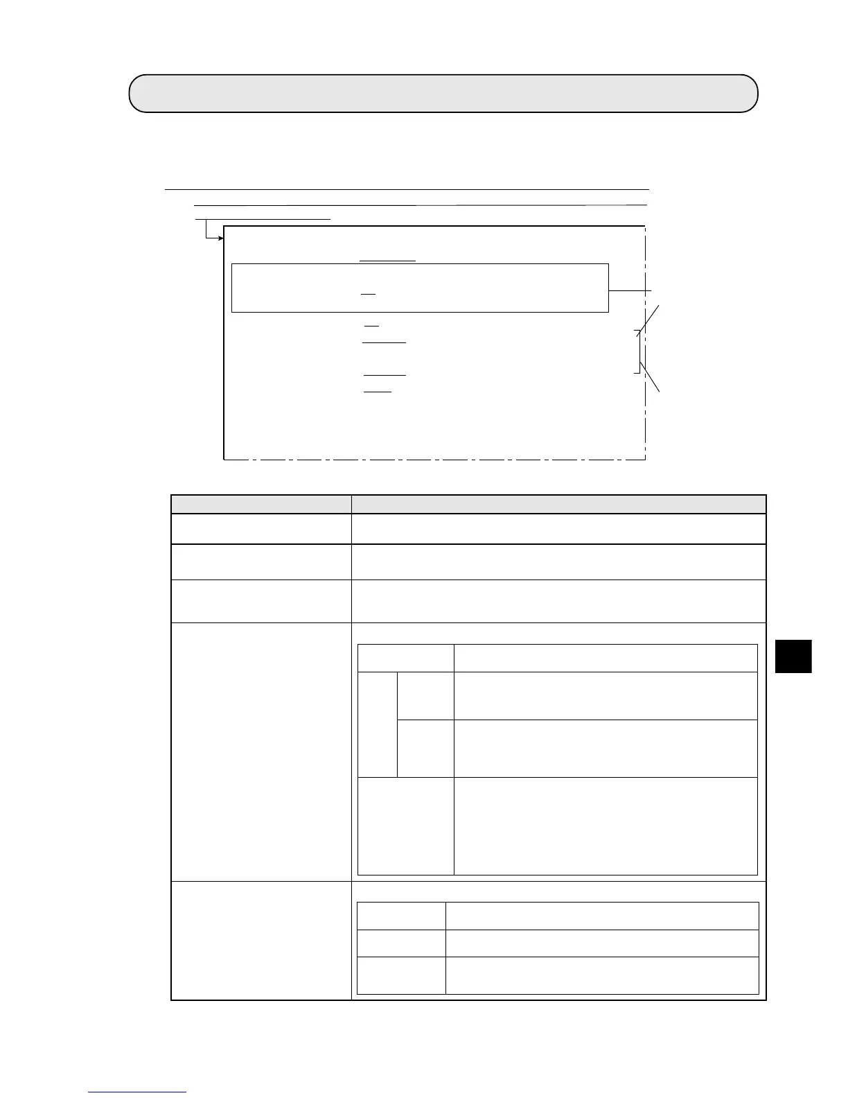
This chapter explains the input/output settings on the IV-S20. The conditions are set on the [IN/OUT
CND.] menu.
1MEAS TRIG INP I/F
(measurement start input)
2
3
Select an input interface for starting the measurement on the IV-S20.
Input/output condition Setting details
The display of item 2 and 3 depends on the setting in item 1 MEAS TRIG
INP I/F. -See Item (1) on the next page.
Select the type of input terminal (INPUT) X5.
5PARALLEL INPUT X5*
(Parallel input X5)
4CHG MEAS NO. X5, X6
(Measurement No. switching
X5 and X6)
Select the type of input terminal (INPUT) X6.
6PARALLEL INPUT X6*
(Parallel input X6)
See the next page.
On the [MAIN OPS MENU], move the cursor to SET-SCRN, and press the SET key.
-On the [SYSTEM SETUP] menu, move the cursor to item 3 I/O CONDITIONS
and press the SET key.
Turn ON or OFF the input terminals (INPUT) X5 and X6 to specify the
measurement number. - See item (2) on the next page.
tupnilanretxE
.langistupnilanretxenasalanimretehtsesunoitcnufCPehT
).01retpahCeeS(
-tsigeR
re
-erefer
ecn
egami
-erusaeM
tnem
3ot0
SPONIAM[ehtnoNOotFFOmorfdehctiwssi5XnehW
ehtrof)ylnorebmunnoitartsiger(egamiecnerefereht,]UNEM
niderotseblliw)2/1aremac(margorptnemerusaemdeificeps
.yromemhsalf02S-VIeht
-aluclaC
noit
neewteb
segami
neercsDNOCEPYTTCEJBOehtno5XtupnilellarapehtnehW
rofderetsigerylsuoiverptaht,egamiecnerefereht,NOsi
hsalf02S-VIehtniderotssi,segamineewtebnoitaluclac
-9ot42-9egapeeS>=segamineewtebnoitaluclaC(.yromem
).72
laniffonoitcerroC
tnemegdujaera
DNOCEPYTTCEJBOehtno5XtupnilellarapehtnehW-
ehtfoynaerastnemerusaem02S-VIehtfidna,NOsineercs
tnemgdujaeralanifehtfostimilrewoldnareppueht;sgniwollof
.oitardeificepsehttayllacitamotuadetcerroceblliwsnoitidnoc
)%05ot0:egnaroitarnoitcerroC(
aerayraniB:stnemerusaemelbitapmocnoitcerroC-
yranibretfastcejboforebmungnitnuoc,tnemerusaem
yranibretfa)gnilebal(noitacifitneditcejbodna,noisrevnoc
.noisrevnoc
tupnilanretxE
eeS(.langistupnilanretxenasalanimretehtsesunoitcnufCPehT
).01retpahC
tuptuoegamI
gnihctiwsaremac
eeS(.dehctiwssi]UNEMSPONIAM[ehtnognittesrotinomehT
).8retpahCnirotinomtuptuO]1[meti
aremaC
tnemerusaem
.oNaremacdengissaehtrofmargorptnemerusaemehtylnosnuR
si2aremac,NOsi6Xnehw,1aremac,FFOsi6XnehW(
)detceles
1
MEAS TRIG INP I/F PARALLEL SERIAL CCD-TRIG
3
SERIAL OUTPUT NO PC-LINK SERIAL
(INPUT=PARALLEL)
4
CHG MEAS NO.X5,X6
NO YES
5
PARALLEL INPUT X5 EXT-INP. REG-REF-IMG(MSR0 COMPARE IMAGES)
6
PARALLEL INPUT X6 EXT-INP. CHG-IMG-OUT-CAM CAM-MEAS
7OUTPUT STATUS
BUSY READY
8
SERIAL CONDITIONS
(TO NEXT SUB-MENU)
9
COMPUTER LINK (TO NEXT SUB-MENU)
0
GAIN OFFSET (TO NEXT SUB-MENU)
q UPPER MENU
[I/O SETTING]
T-ARA EVALUATION ADJ.(00%)
After selecting
REG-REF-IMG,
change MSR0
to MSR3 using
the up/down
keys.
Items 5 and 6
are not displayed
when item 4 has
been set to YES.
* Items 5 and 6 can be selected when 4 CHG MEAS NO. X5, X6 is set to NO.