14-2
Computer Link
14
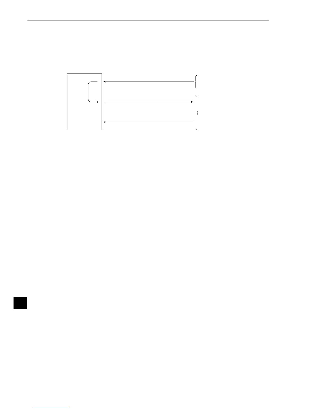
14-2 Data flow
Specify the CCD-TRIG (camera 1) or the PARALLEL (parallel interface). as the source of the MEAS TRIG
INP I/F (measurement start input) signal. (See Chapter 11 "Input/Output Conditions Settings.")
The data flow for a measurement start input (CCD trigger/parallel) signal and an object type change
command (parallel) is shown below.
IV-S20
Measuring
1 Enter measurement start signal.
(CCD trigger/parallel)
3 Receive a completion response.
2 Write measurement data.
PC
(2), (3): Computer lin
CCD camera or PC
The block of measurement data to be written from the IV-S20 to the PC, in step 2, can be specified on
the [OBJECT TYPE I/O] menu. (See page 11-21.)
[When a Sharp PC is connected]
The IV-S20 sends write enable command (EWR) to the PC in the following cases.
- When the power is applied to the IV-S20.
- When a Sharp PC is selected.
- When a write mode nonconformity error (code 10
(H)
) occurs after a result write command (WRG) is
transmitted (when the power is disconnected from the PC).
[When a Mitsubishi or OMRON PC is connected]
The data in items 2 and 3 are divided into packets for transmission.