8-1
Run Menu Conditions and Settings
8
[1] Output monitor
When two cameras have been connected to IV-S20, you can switch back and forth between the image
from the cameras on one monitor. Also, the monitor screen can be divided into two parts to display the
two images simultaneously.
- Purpose of the setting
To set the conditions in which an image captured during measurement will be displayed on the run
menu.
- Output monitor switching
The monitor can be switched by two methods, i.e. key pressing or parallel input.
(1) Output monitor switching by key presses
To specify a monitor, select the 1 MONITOR OUTPUT and 2 CAMERA1&2 options you want on
the [RUN MENU SETTINGS] menu.
[Operation procedure]
1. On the [RUN MENU SETTINGS] menu (shown above), move the cursor to item 1 MONITOR
OUTPUT with up and down keys, and press the SET key.
2. Move the cursor to CAM1, CAM2, or CAM1&2 with the left and right keys, and press the SET key.
(If CAM1&2 is specified, continue with steps 3 and 4.)
3. Move the cursor to 2 CAME1&2, with the up and down keys, and press the SET key.
4. Select CAM1 or CAM2 with the left and right keys, the select UP, MD or LO for each camera with the
up and down keys, and press the SET key.
[Display examples on the MAIN OPS MENU]
MAIN OPS MENU condition
Description of setting (selection)
1
MONITOR OUTPUT
2CAMERA1&2
· Item 2 will be displayed if CAM1&2 has been selected in item
1
.
Select the camera whose image will be displayed on the screen.
· If CAM1&2 is selected, the picture taken by camera 1 will be
displayed on the upper half of the screen, and the picture taken
by camera 2 will be displayed on the lower half of the screen.
Each images taken by cameras 1 and 2 is divided into three
parts, i.e. the upper, middle and lower parts. Select the part you
want displayed on the screen. (When CAM1&2 has been speci-
fied in
1
MONITOR OUTPUT.)
Indicates camera 1.
When CAM2 is selected for
1
MONITOR OUTPUT, C2 will be
dis-played, and when CAM1&2
is selected, “1&2” will be dis-
played.
On the MAIN OPS MENU, move the cursor to SET-SCRN item, and press the SET key
- On the [SYSTEM SETUP] menu, move the cursor to item
1
OPS MENU SETTING
and press the SET key.
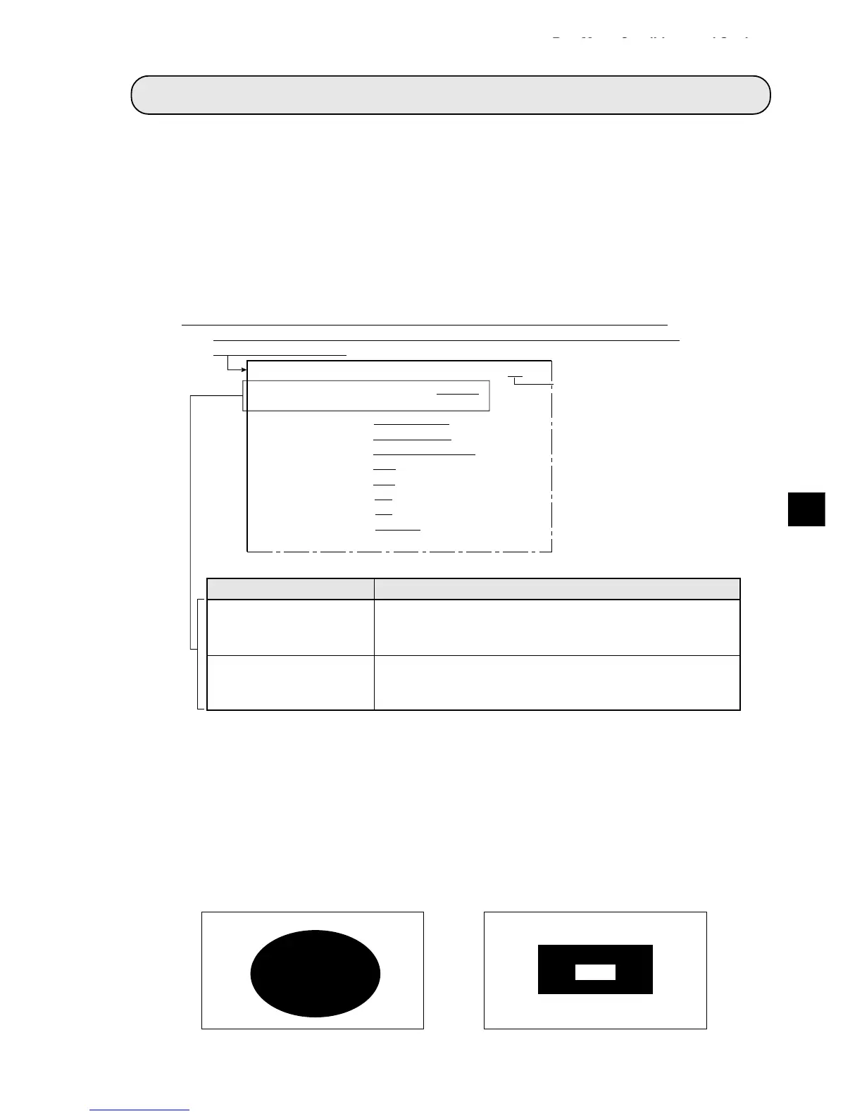
1MONITOR OUTPUT CAM1 CAM2 CAM1&2
2CAMERA1&2
CAM1=MD CAM2=MD
3CAPTURE AN IMAGE PARTIAL-IMAGE WHOLE-IMAGE NO
4MESSAGE DISPLAY
YES(RESULT.OK) YES(RESULT.NO) NO
5PATTERN DISPLAY MEAS-RESULT- OUT NO
6SHOW BINARY IMAGE
YES NO
7SHOWCORRECTIMG
YES NO
8DISPLAY + CURSOR
NO YES MANL-MESR
9OBJ.NO.MANL MODE
NO YES
0IMAGE DISPLAY FREEZE THROUGH
qUPPER MENU
[RUN MENU SETTINGS]
FC1L
C1ALL C2NO C1NO C2ALL
· Camera 1 on the whole screen
(When CAM1 has been specified in item
1 MONITOR OUTPUT)
· Camera 2 on the whole screen
(When CAM2 has been specified in item
1 MONITOR OUTPUT)
Chapter 8: Run Menu Conditions and Settings