8-2
Run Menu Conditions and Settings
8
· Set PARALLEL INPUT X6 to CHG-IMG-OUT-CAM.
· Every time the signal X6 is turned ON from OFF, camera display will be switched.
· An the example of the display on the MAIN OPS MENU is the same as that shown in
Item (1) above “Output monitor switching by key input.”
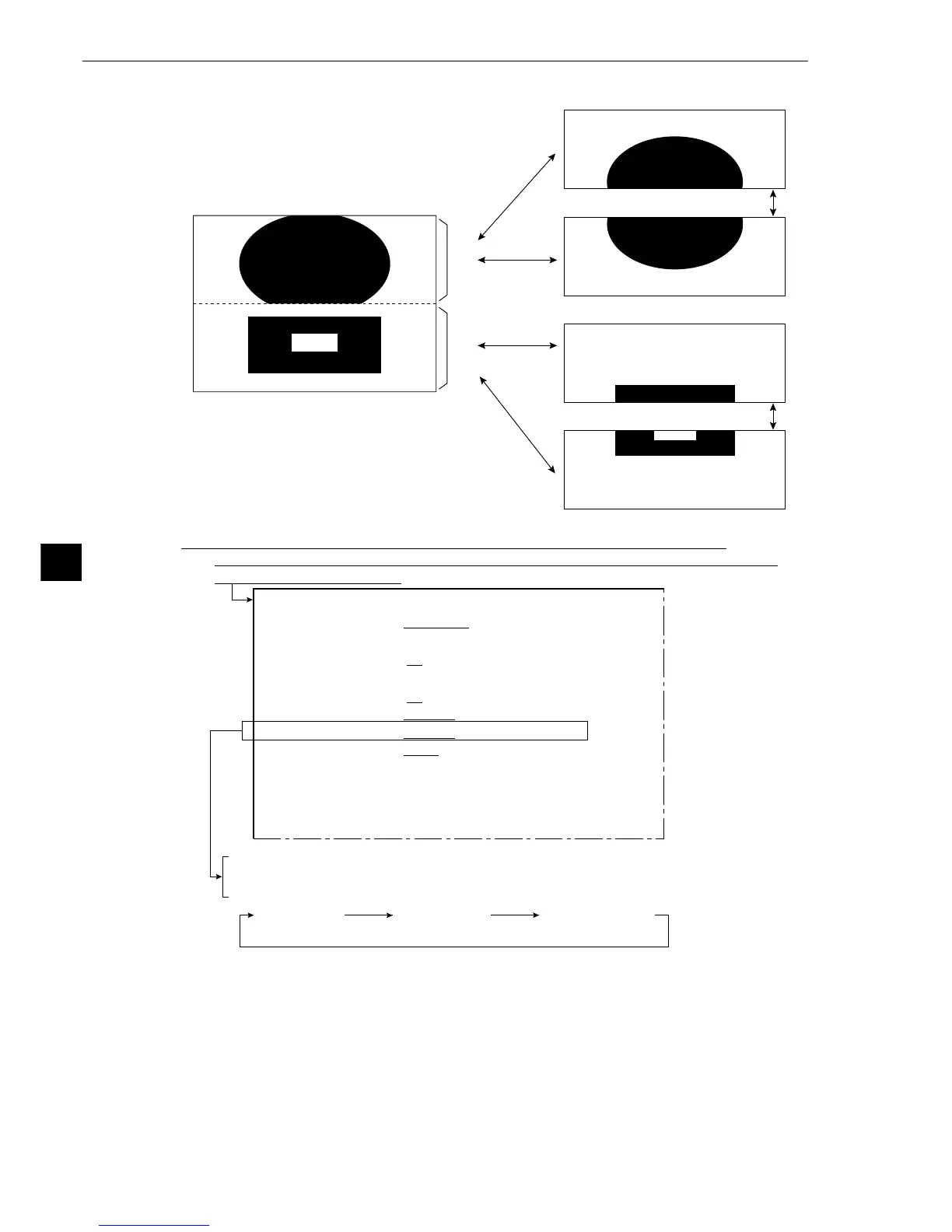
Camera 1 on
the whole screen
Note: You can change the display part of the image from the CAM1 & 2 to the
UP, MD or LO by key input or by using a general-purpose serial interface command.
On the [MAIN OPS MENU], move the cursor to SET-SCRN item, and press the SET key.
⇒Move the cursor to 3 I/O CONDITIONS (input/output conditions) on the [SYSTEM SETUP]
menu, and press the SET key.
1MEAS TRIG INP I/F PARALLEL SERIAL CCD-TRG
3SERIAL OUTPUT NO PC-LINK SERIAL
(INPUT-PARALLEL)
4CHG MEAS NO.X5,X6
NO YES
5PARALLEL INPUT X5
EXT-INP. REG-REF-IMG(MSR0)
6PARALLEL INPUT X6
EXT-INP. CHG-IMG-OUT-CAM CAM-MEAS
7OUTPUT STATUS BUSY READY
8SERIAL CONDITIONS(TO NEXT SUB-MENU)
9COMPUTER LINK (TO NEXT SUB-MENU)
0GAIN-OFFSET (TO NEXT SUB-MENU)
qUPPER MENU
[IN/OUT SETTINGS]
· Item 2 is displayed when CCD-TRG. (CCD trigger) has been specified in item 1.
Camera 2 on
the whole screen
Cameras 1 and 2
on a divided screen
(2) Output monitor switching by parallel input
C1MD
C2MD
C1UP
C1LO
C2UP
C2LO
· Simultaneous display on a divided screen
(When CAM1&2 has been specified in item 1
MONITOR OUTPUT.)
When CAM1 has been set to UP
When item 2 CAMERA1&2, has been
set to CAM1=MD CAM2=MD
When CAM1 has been set to LO
When CAM2 has been set to UP
When CAM2 has been set to LO
Screen for
camera 1
Screen for
camera 2