10-13
PC Function
10
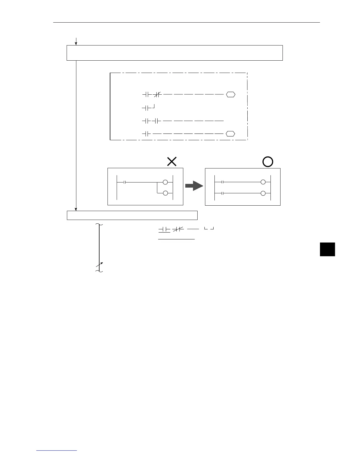
(4) Create a ladder circuit for the page numbers registered in s.tep (1) repeating the
operations given in steps (2) and (3).
Creation example:
Note: Output relays cannot be used in series on a ladder circuit. Change circuit a to
circuit b.
(5) Storing the circuit in the IV-S20 memory (RAM)
1. Move the cursor to item 6 UPPER MENU with the up and down keys, and press the SET key.
- The screen will return to the [OBJECT TYPE COND] menu, and the ladder circuit creation
process will be finished.
[PAGE0]
INPUT0
LOGIC
INPUT1
LOGIC
INPUT2
LOGIC
INPUT3
LOGIC
10 234567OUT
C000
Y00
C001
C001
X0
X1
TM0
Y01
TM0
0150
From the preceding page
1
4LOGICAL SYMBOL
5OUTPUT SIGNAL OUT Y00(0~15) AUXRLY C000(0~127)
TMR TM0(0~7) SET-VL000(000~999)
CNT CN0(0~7) SET-VL000(000~999)
DEL.
6UPPER MENU
DEL.
C010
C001
C011
Circuit a
Circuit b
C010
C001
C011
C001