11-5
11
Setting the Input/Output Conditions
1MEASTRIGINPI/F
PARALLEL SERIAL CCD-TRIG
3SERIAL OUTPUT
NO PC-LINK SERIAL
(INPUT=PARALLEL)
8
SERIAL CONDITIONS
(TO NEXT SUB-MENU)
9
COMPUTER LINK
(TO NEXT SUB-MENU)
[I/O SETTINGS]
· Setting order
1
→
3
→8→9
Programmable
controller
(X1 to X4)
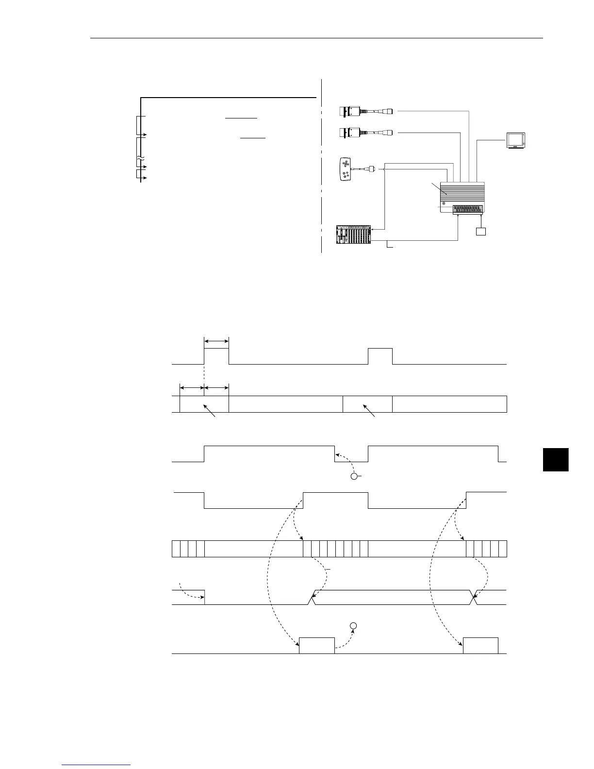
· Configuration example
External trigger X0
(photo sensor or
proximity sensor)
IV-S20 main
housing
Power supply
(24 VDC)
Monitor
Camera 1 (image capturing)
Camera 2 (image capturing)
Remote keypad
Data
(Computer link)
Object type change
(parallel IF)
- The data in a specified block No., set in item 5COMPUTER LINK OUT & SERIAL
OUTPUT on the [OBJECT TYPE I/O] menu, will be output through the computer link. (See
page 11-20.)
- Time chart
(2) Measurement start input = parallel, object type change = parallel, result output = computer
Iink/parallel
* When a Sharp PC is used, a write enable command (EWR) is transmitted from the IV-S20 to
the PC in the following cases.
- When the power is applied to the IV-S20
- When a write mode nonconformity error (code 10
(H)
) occurs after a result write command
(WRG) is transmitted (when the power is disconnected from the PC)
- When the output method is changed from the serial interface to the computer link
Terminate
measurement
(C119)
P
C
P
C
P
C
P
C
P
C
P
C
P
C
P
C
P
C
P
C
P
C
P
C
P
C
P
C
P
C
P
C
P
C
Result output
Result
output
Result
output
Result output
Measurement
start input
(X0)
10 ms
or more
10 ms
or more
10 ms
or more
Object type
number input
(X1 to X4)
Specified object type number Specified object type number
BUSY output
Computer link outputoutput
Measurement result is valid at the end
of a measurement
BUSY signal is turned OFF at the
conclusion of the result output.
PC calculation
condition
Halt PC operation during
measurement
Halt PC operation during
measurement
When the object type is
changed, all Y output and
auxiliary relays turn OFF.
Parallel output is valid for
PC control after the
measurement result is
determined.
Parallel output
(Y0 to Y7)
a
a