14-31
Computer link
14
[Explanation of the program]
The numbers 1 to 16 below correspond to the same numbers on the preceding page.
1. Turn on the power, and wait for 5 sec. (07377 is kept ON for only 1 scan after the power is
turned ON.)
2. The camera is started. (00040 enters a measurement trigger.)
3. The trigger input (00007) is self-latched when the operation start has begin (00000 = ON).
4. The termination code of the write register is cleared.
5. The time-out detection timer monitoring the computer link is started.
6. Time-out error
7. A check is made for normal termination.
8. Normal termination (09000 = 000
(8)
)
9. A check is made for errors.
10. Occurrence of an error (09000 = 001 to 376
(8)
)
11. The data in the result output relays Y0 to Y15 (16 points) on the IV-S20 is transferred from
registers 09004 to 09005 to addresses ]0412 and ]0413.
12. A normal termination signal is output.
13. The judgment (OK/NG) of the result output relay Y0 is output.
14. The judgment (OK/NG) of the result output relay Y1 is output.
15. When a time-out or an error occurs, it is output.
16. When a time-out or an error occurs, it is reset.
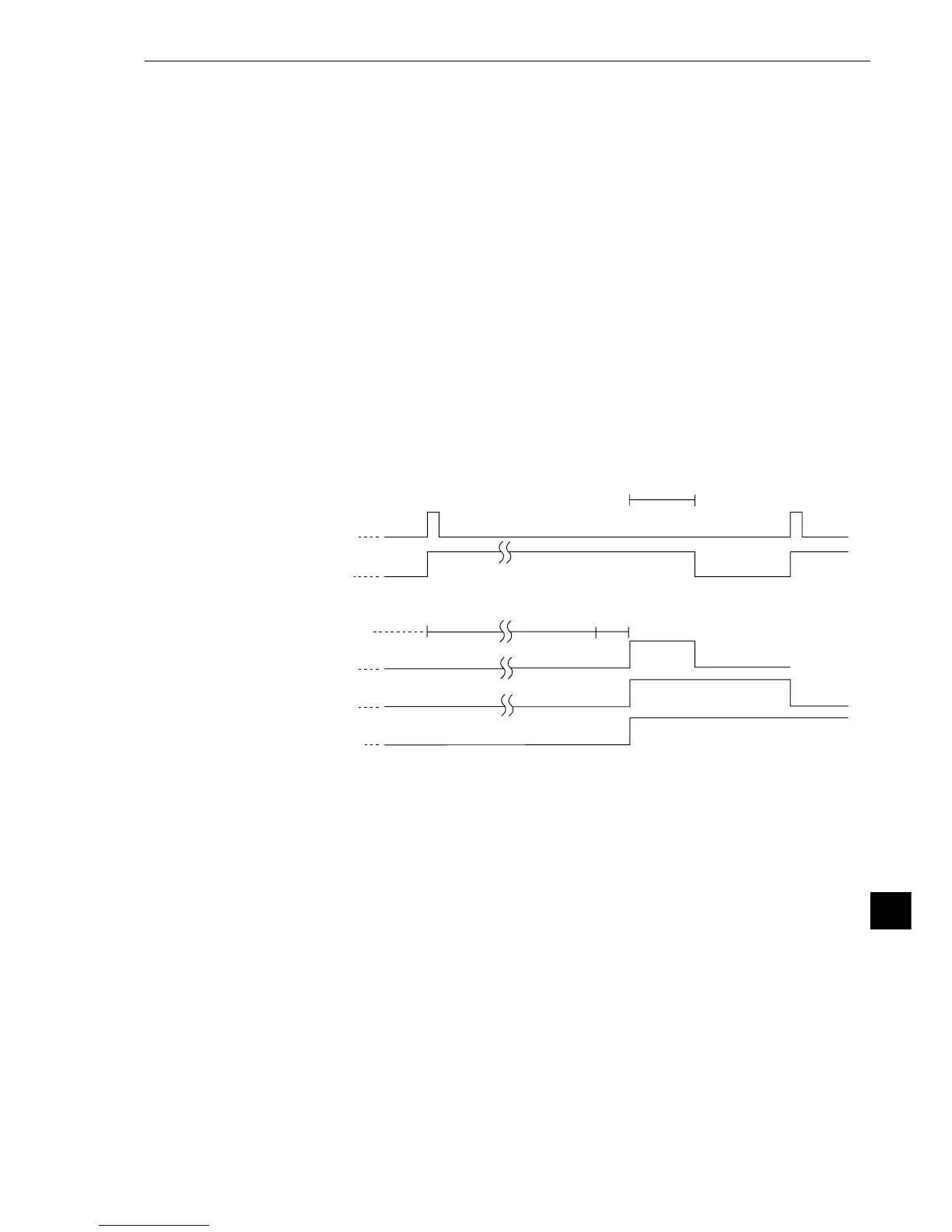
(4) Timing chart
Operation start 00040
Start signal input 00007
1 scan time
Operation of the IV-S20
through a computer link
Y0, Y1
Normal termination
04100
IV-S20 - JW70H
Execution of
measurement
Error output 00013
OK
Data writing