133
6.6. Speed control mode
Speed control is often applied for occasions where is CNC machine, drilling machine, etc. The
command source is analog signal or inner register. The analog signal is the external voltage. The inner
command is performed by the following 2 ways: (1) Use the inner registers (PC05 to PC11) to set the
various commands then switch SP1, SP2, and SP3 to change the demand speed. (2)Use the
communication software to modify the value of speed command register.
To avoid the discontinuity, the drives afford users the smooth S-pattern running. There are 2
control modes (manual and automatic) available. The manual mode enables users to set all related
parameters while the automatic functions were off. The automatic mode provides an estimation of load
inertia ratio and parameters adjusted. In addition, an simple mode is designed to provide users a robust
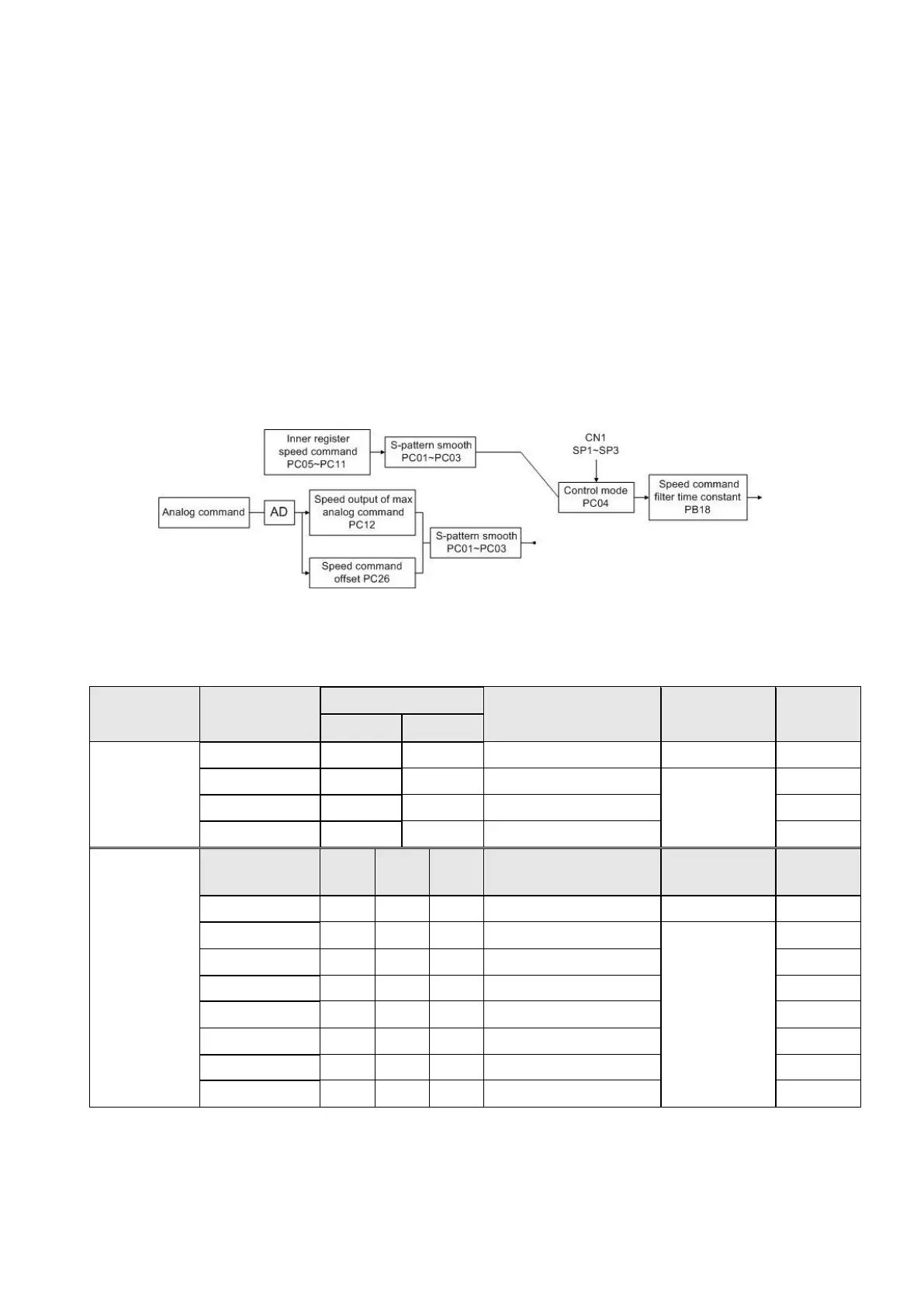
control which could instantaneously suppress external load interference. The basic speed control
blocks are shown as below.
The S-pattern smooth process and speed filter are recommended to suppress the discontinuity.
6.6.1. Selection of speed command
There are 8 combinations which are listed below for user to choose.
SP3 is invalid
(default value)
(*) 0: OFF (SCx-SG is open-circuit) 1:ON (SCx-SG is short-circuit), x=1~7
 Loading...