15
3.2. Description of drive terminals and sockets
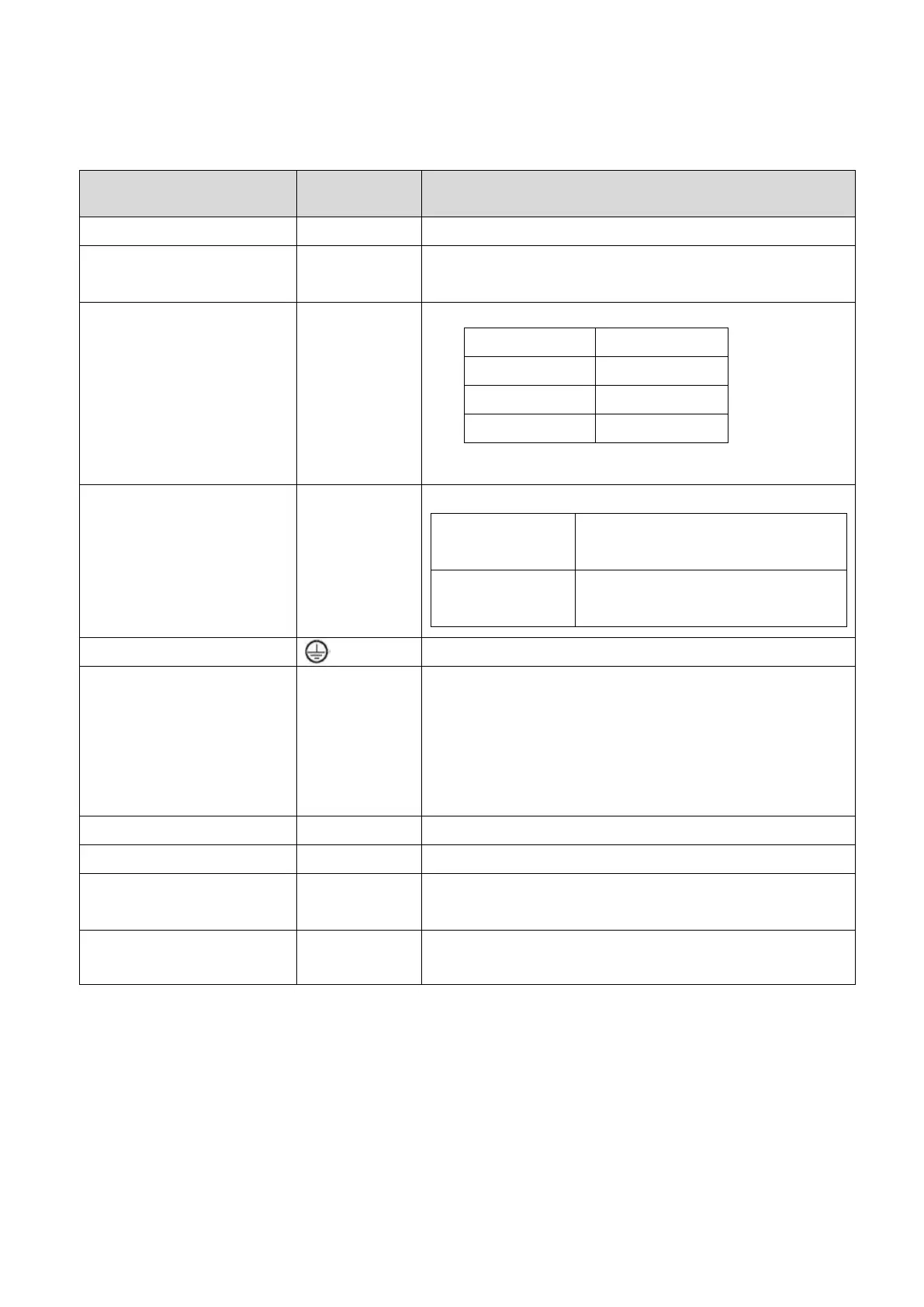
Main power input terminal
Connect to 3-phase AC power source
Control power input
terminal
Connect to single phase AC power source
P/C connected to resistor and
P/D open.
P/D connect together and make
P/C open.
To connect the power ground with the motor ground.
P: + terminal
N: - terminal
When an active brake device is used for 1.5KW or
above, please connect the + terminal of it to the
drive‟s P terminal, the - terminal to the drive‟s N
terminal. The active brake device is usually applied
when the huge regenerative power produced by the
servo motor in heavy duty.
Connect to the host controller.
Connect to the encoder cable of servo motor.
Connect CN3 to the superior device and CN3L to the
inferior device.
Connect to the USB port of PC.
Follow the description below when wiring:
1. Keep the power lines R/S/T and U/V/W away from other signal lines at least 30cm.
2. Do not touch the power lines until the charge indicator goes out. When “power off”, there is a large
amount of electric charge in the aluminum capacitors inside the servo drive.
3. If a longer encoder cable is required, uses the twisted pairs cable and not to exceed 20m. Be sure
to upgrade the diameter of wires to avoid signals attenuated when the wire‟s length greater than
20m.
 Loading...