154
6.8. Control mode switch
SDE servo drives provide 5 modes switch to fit users who need to change varied modes
frequently. The PA01 could be changed for the control mode switch. See the table below.
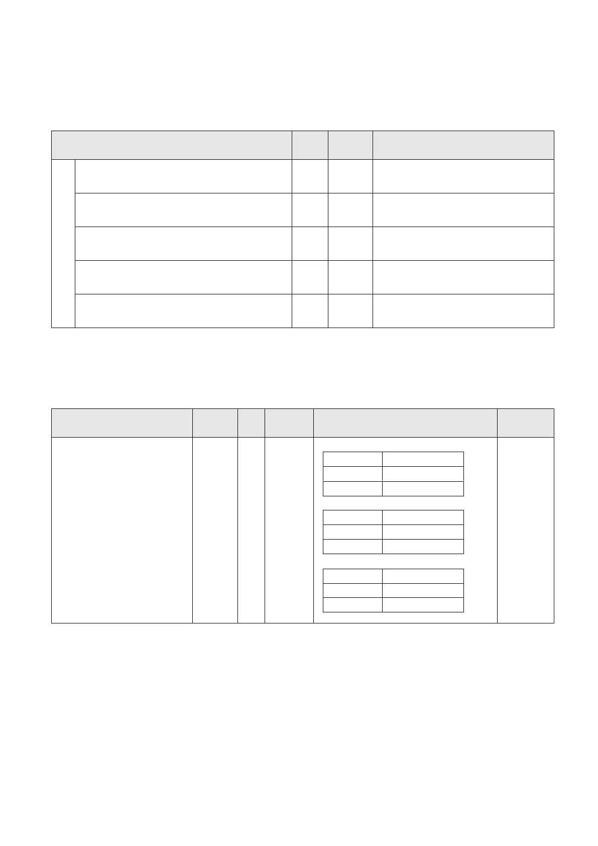
Position with external command - speed
Use DI signal to switch Pt and S
Position with external command - torque
Use DI signal to switch Pt and T
Position with inner register command - speed
Use DI signal to switch Pr and S
Position with inner register command - torque
Use DI signal to switch Pr and T
Use DI signal to switch S and T
The arrangement of DI and DO is critical when the control mode switch is applied. To avoid DI/DO
pins insufficient, users could apply external analog voltage signal as speed or torque command so that
could reduce the demand of DI.
The LOP function should be made valid once control mode switch is applied. See the following table.
Option of position/speed switched
Option of speed/torque switched
Option of torque/position switched
(*) 0: OFF (LOP-SG is open-circuit), 1:ON (LOP-SG is short-circuit)
Note: The pin function setting of ST1 and RS2 are the same value, as speed/torque mode switch is
applied and the LOP signal activated, the ST1 function would have priority in speed control mode
and the RS2 function would have priority in torque control mode. Others such as POS1/SP2,
PC/ST1, RS2/PC, TL/ST2, ST2/RS1, RS1/TL, CR/SP1 are defined mutually. The drive would
automatically recognize the corresponding DI pin function when 2 different modes are switched.
See Section 3.3.4 for more details.
 Loading...