157
6.9. Other functions
Before wiring, turn off the power and wait for 10 minutes or more until the charge
LED turns off. Otherwise, an electric shock may occur.
Use the specified auxiliary equipment and options to prevent a malfunction or a
fire.
6.9.1. Selection of brake resistor
Use the specified auxiliary equipment and options to prevent a malfunction or a
fire.
As the direction of motor generated torque is opposite to the rotary direction of motor, it
becomes a power generator. The regenerative energy would be turned back to the servo drive. To
prevent from P-N voltage exceeded, a voltage stabilized protection is necessary. The IGBT switch and
brake resistors constitute this protection. Regenerative energy is consumed by the brake resistor.
There is a built-in brake resistor inside the drive (below 3.5KW). If the regenerative energy is too
large, it is not recommended to use. Instead, use an external one to avoid overheating. When using the
built-in brake resistor, make sure that the P/D terminals is short-circuit. If the external brake resistor
applied, make P/D terminals open while the external resistor is connected to the P/C terminals.
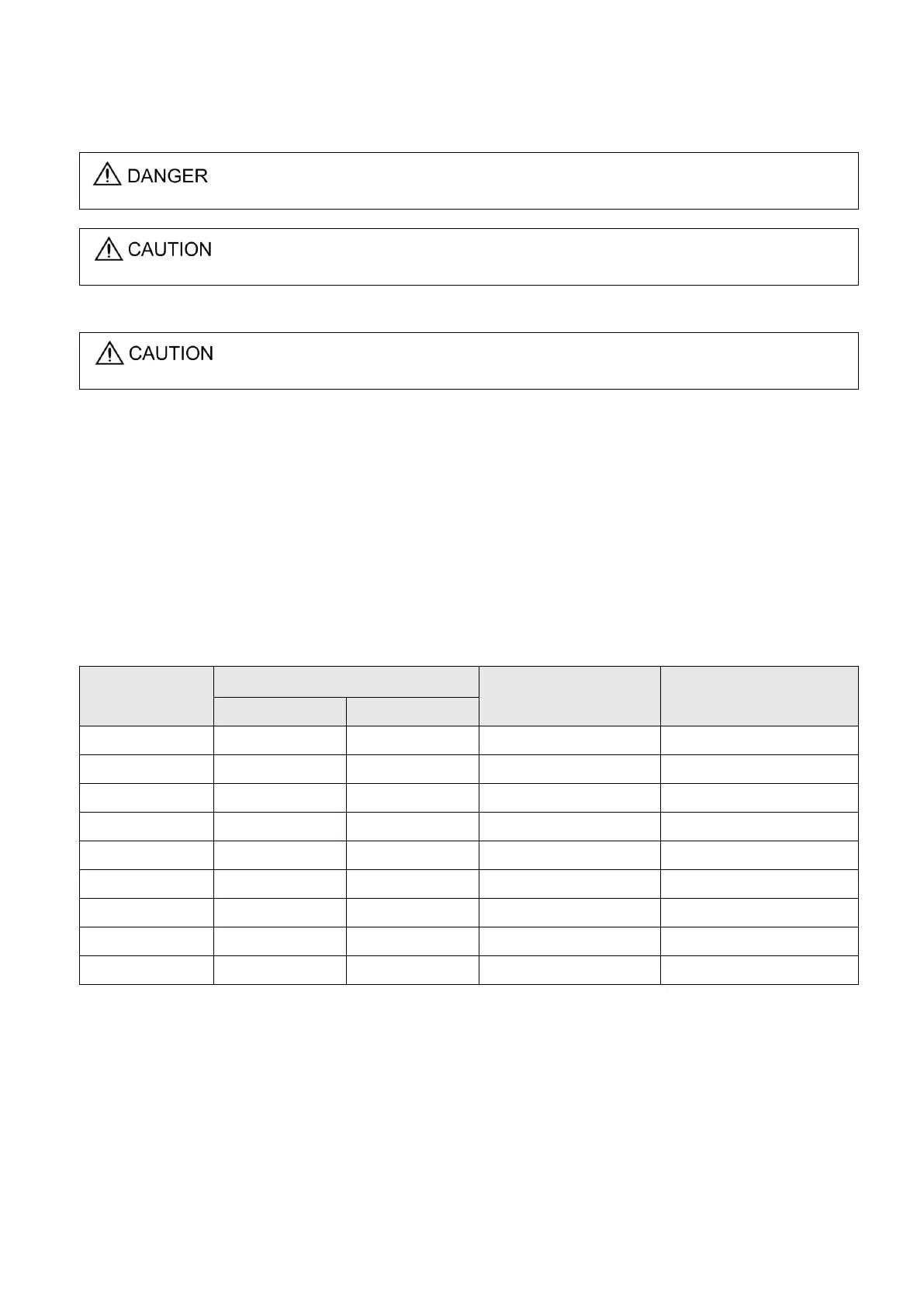
Built-in brake resistor specifications for the Shihlin servo drive are described below.
Built-in brake resistor specification
Consumption power of
built-in resistor (W)
Note: The average regenerative power that could be consumed is at 50% rated power of the built-in
brake resistor. So are the external brake resistors.
As external brake resistor is applied, the same resistance value mentioned above is required. If
serial or parallel wiring are applied to increase resistor‟s power, be sure that the resistance meets the
minimum permissible specification. The brake resistor with a thermal switch or a cooling fan would be
helpful to tell users that the capacity of brake resistor is insufficient or to reduce the temperature of
brake resistor. Please contact the manufacturer of brake resistor to know the detail load characteristic.
 Loading...