8
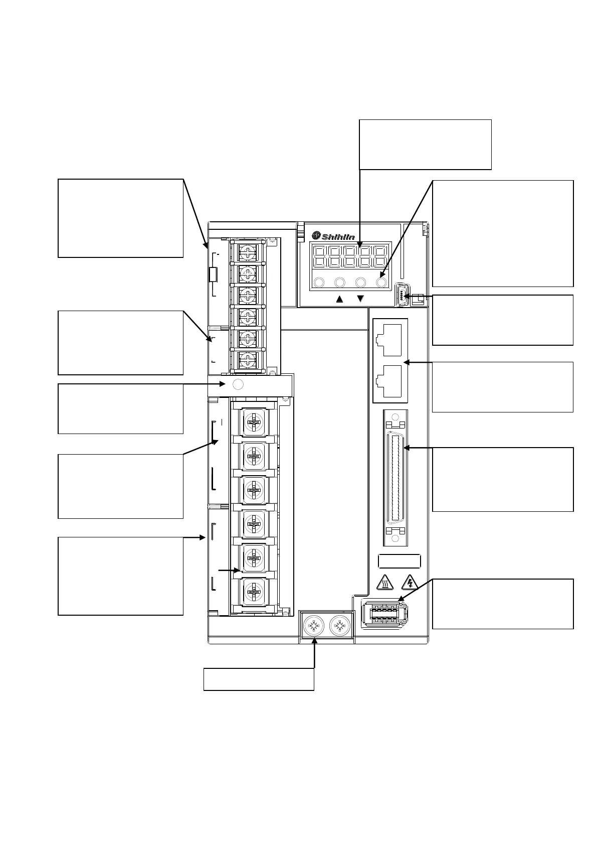
1.10 Drive appearance and panel descriptions (1.5kW or greater)
Note: 1. If an external brake resistor is applied, please make sure that “P” and “D” connect to the
resistor, and make “P” and “C” open. If an active brake unit is applied, connect “P” and “N” to
the unit and make “P” and “C” and “D” open.
SDE-300A2
+P
D
BR
C
-N
MODE
SET
CN3
CN3L
CN4
CHARGE
R
L1
220V
L2
S
T
U
MOTOR
V
W
220V
CN1
CN2
Display:
Drive status, alarm number,
parameter are displayed.
Operation keys:
Parameter setting, monitoring
etc. are executed with 4 keys.
MODE:
mode selection
▢ :
▼ : -1 decreased key
USB port:
Connect a PC or compatible
superior controller.
Power indicator:
To indicate the remainder
voltage of servo drive.
50-pin DI/DO socket:
An I/O signal socket with
particular signals for various
applications
Encoder socket:
Used to connect the servo
motor encoder
Brake resistor terminals:
Install an external resistor
if large inertia load applied
and frequent regeneration.
(Note 1)
Main power input:
Connect R/S/T to
commercial 3 phase AC
200~240 volt 50/60Hz.
Output power terminals:
Connect U/V/W to servo
motor in sequence. Do not
confuse U/VW with R/S/T,
it cause damage.
USB port:
Connect a PC or compatible
superior controller.
Auxiliary power input:
Connect L1/L2 to the
single phase AC 200~240
volt power 50/60 Hz.
 Loading...