14
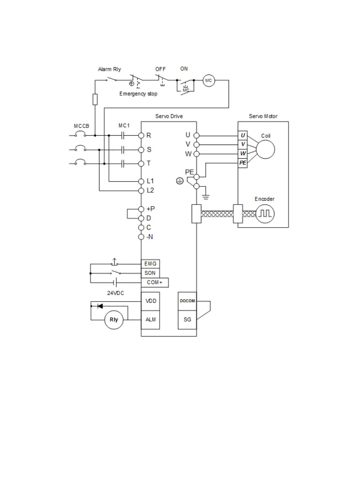
3.1. Input power source circuit
Note: 1. If an external brake resistor is applied, please make sure that “P” and “D” connect to the
resistor, and make “P” and “C” open. Or an active brake unit is applied, connect “P” and “N”
to the unit and make “P” and “C” and “D” open.
Note: 2. For the encoder cable, use of the option cable is recommended.
Note: 3. This diagram is for sink input diagram.
Note: 4. This diagram is for source output diagram, .make “ DOCOM” and “SG” short together. And use
“VDD” for a 24VDC power source.
 Loading...