138
6.6.5. Adjustment of speed loop gain
There are some parameters related to inner speed control loop for users to adjust. Set the value
of the PA02 to use the auto-gain tuning function or manual-gain tuning function. If auto-gain tuning
function is performed, the load inertia ratio would be approximated continuously and the control gain
value would be set automatically. If manual-gain gain tuning is performed, users have to enter the
proper value of the load inertia ratio and control gain value. At this time, all automatic or auxiliary
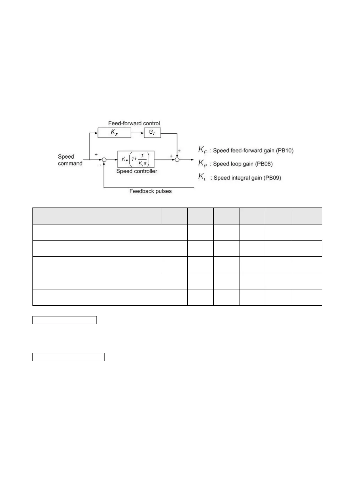
functions about inner speed control loop would be disabled. The block diagram of inner speed control
loop is presented as follows:
Parameters and settings related of this mode are presented below.
Auto-tuning response level setting
Auto-gain tuning mode
The drive would tune the optimum gains during the acceleration/deceleration route. Refer to
section 5.3.2 for further details.
Manual-gain tuning mode
When the PA02 value is 0000h or 0001h, the effective parameters are: speed loop gain(PB08),
speed integral gain(PB09) and speed feed-forward gain (PB10). When PA02 is set as 0001, the servo
drive would automatically enable an interference compensator. This function could reduce torque
ripple, overshoot and speed ripple. It is suitable for systems with load changed violently. Besides, users
should avoid applying this compensator on the system which the ratio of load inertia to motor shaft is
greater than 10 times. If necessary, the related parameters should be adjusted according to the various
cases. The schematic diagram is as follows.
 Loading...