49
4.5. Diagnostic display
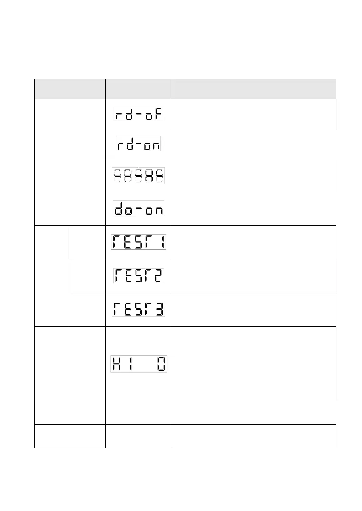
The following table provides information display related to the diagnostic mode.
Not ready yet.
The drive is being initialized, an alarm has occurred or the
SON DI is not activated.
Ready.
Initialization completed; the drive is ready for operation.
External I/O signal
display
Indicates the ON/OFF states of the external I/O signals.
The upper segments correspond to the input signals and
the lower ones to the output signals. The I/O signals could
be changed by the modification of PD group parameters.
Digital output signals could be forced ON/OFF.
JOG could be executed if there is no external command.
Positioning could be executed when there is no external
command. The PC communication software via RS-485 or
USB is required.
This operation could be executed the estimation of load to
motor inertia ratio or related gain values. This operation
cannot be performed with the display panel.
Automatic offset of
analog input
The offset voltages causes the motor to rotate slowly at the
speed analog command 0V or speed analog limit 0V, this
calibration makes a zero level adjustment. When using this
function, the PC26 would automatically save the result.
Please follow the steps to operate.
(1). Scroll to the diagnostic display.
(2). Press the “ SET” key once.
(3). Press the “UP” or “DOWN” key and select 1.
(4). Press the “SET” key.
Indicates the version of the software.
Indicates the system number of the software.
The applications of diagnostic display are described as follows.
 Loading...