161
of motor is reverse rotation -3000 rpm. The mentioned example above is without any adjustment of
PC28 to PC31.
Voltage offset of analog monitor
The parameter PC28 and PC29 are used to set the compensation to eliminate the bias voltages of
analog monitor output MON1 and MON2.
Analog monitor ch1 offset
Used to set the offset voltage of the
analog monitor ch1 output.
Analog monitor ch2 offset
Used to set the offset voltage of the
analog monitor ch2 output.
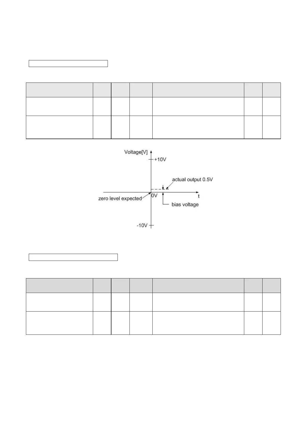
Here is an example.
It assumes that the motor speed is 0 rpm, and then the analog monitor voltage output should be 0 V.
This difference above is 0.5 V, which could be compensated by setting PC28 or PC29 as -500mV so
the MOD analog voltage would be corrected.
Output proportion of analog monitor
The output proportion of analog monitor enables users to set the ratio of the analog voltage output to
be viewed. Relevant parameters are presented in the table below.
Analog monitor ch1 output
proportion
Set the output proportion of analog
monitor ch1.
Analog monitor ch2 output
proportion
Set the output proportion of analog
monitor ch2.
If the current rotation speed is +3000 rpm and monitor scale is ±10V/ (double rated speed), the analog
output should be +5V if MOG1 or MOG2 is set as initial value (100%). So, the analog monitor output
voltage by MON should be +10V in case of 50% setting value applied.
The equation is:
Monitor output = monitoring value monitor scale MOG
 Loading...