Section 8: Wire and Cable Routing • May 2, 2016
© Copyright 2016 ShopBot Tools, Inc. page 8-3
Thread proximity switch into hole until it rests on the target. Back it out
1 to 2 turns so there is a 1/32” – 1/16” (1-2mm) gap between them.
Tighten nuts and connect the Y-axis proximity switch cable (marked
with blue tape).
For best cable routing, the orientation of the three pins in the switch
should resemble an arrow pointing downward.
Screw Y cable carrier onto Y proximity switch.
Route cable up the left side of the YZ car and through the YZ plate.
Secure cable to the YZ plate ange using zip ties in the pre-drilled holes.
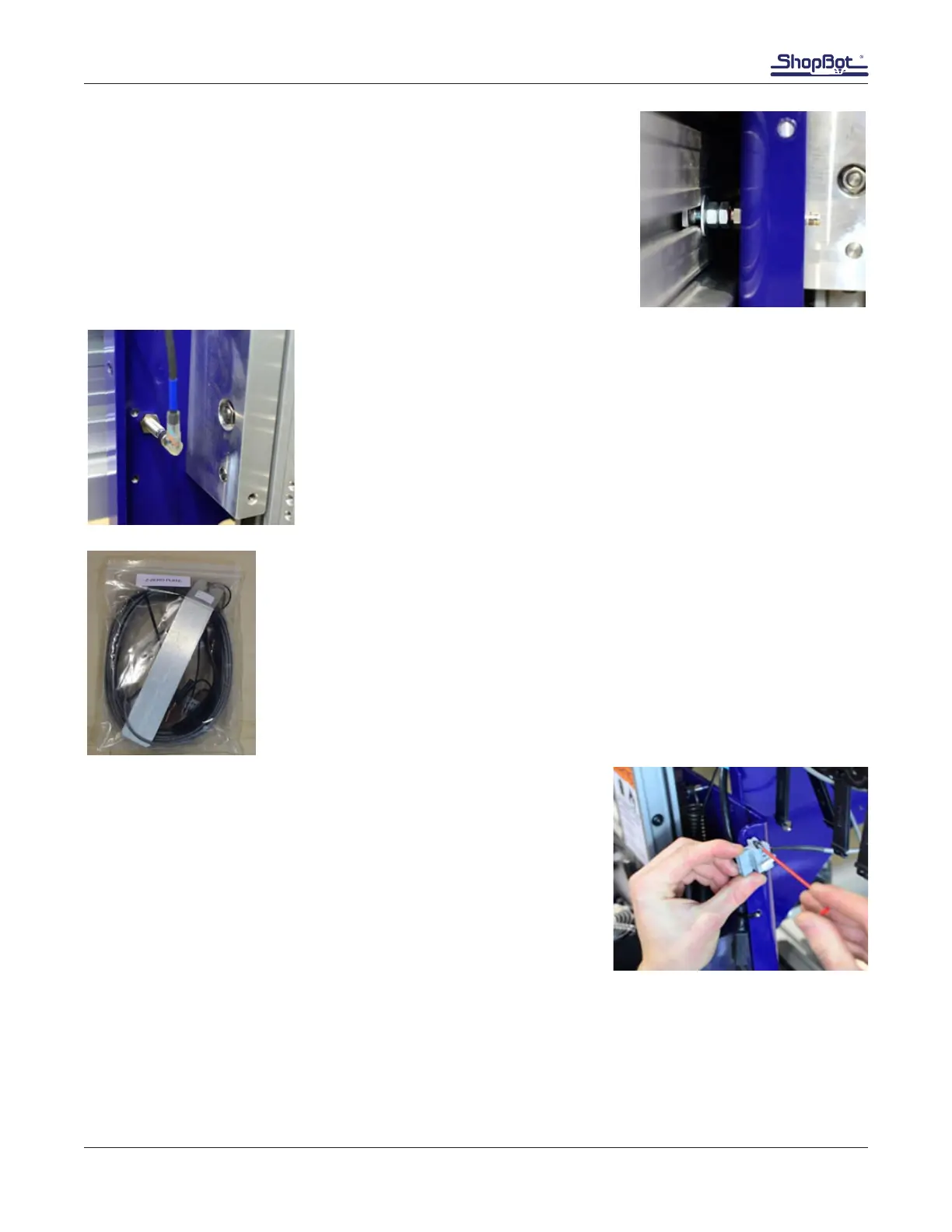
Z Zero Plate Assembly
The Z zero plate assembly allows for accurately calibrating the height of the Z
axis before cutting.
All of the Z zero plate components are packed in a plastic bag inside the box
of accessories.
Locate 30’ gray cable and the two black 3mm screws in the Z zero
assembly kit.
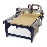
Attach the gray Wago connector to the upper right side of the YZ
plate, as shown in this image.
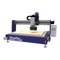
Note: The white plastic hooked piece indicated by the arrow is
known as a Wago tool. It’s used as a fulcrum to release wires from
Wago connector terminals. Store it in a safe place.