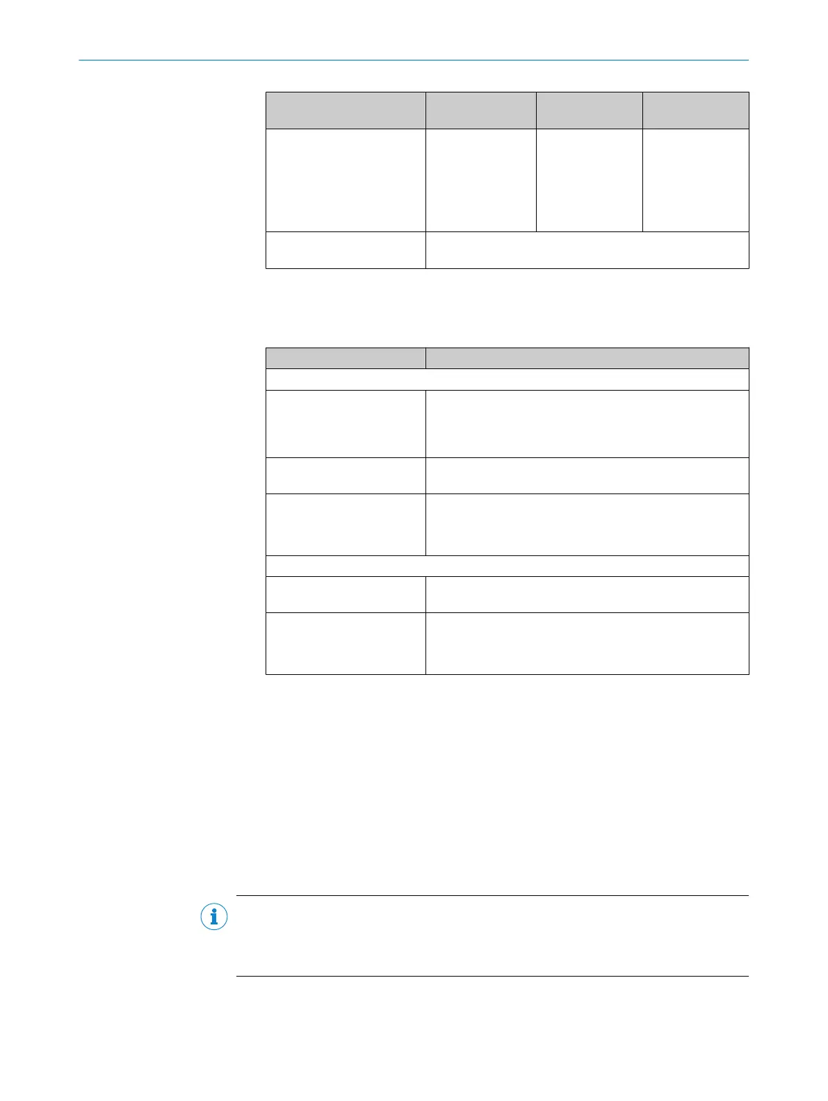
Field Input assembly
instanc
e
Output assembly
instance
Size (in 8-bit
words)
Safety output (from the view
of t
he control)
1278 Dependent on
assembly used:
•
100
OR
•
103
Dependent on
assembly used:
•
Assembly 100:
8
•
Assembly 103:
16
Configuration assembly
ins
tance
1278
6. Define the connection as a unicast connection over EtherNet/IP or as a multicast
connec
tion over EtherNet/IP.
7. Set the parameters for safety.
Table 8: Safety parameters
Field Value
Input (from the view of the controller)
1)
Requested Packet Interval
(R
PI)
5ms (or a multiple of this)
(Useful in many cases: 10ms. Smaller values make net‐
work transmission more prone to errors. Larger values lead
to longer response times.)
Timeout multiplier Depending on the network, the required response times
and t
he required availability
Network delay multiplier Dependent on the complexity of the network:
•
Simple networks can do with lower values
•
Complex networks require higher values
Output (from the view of the controller)
2)
Timeout multiplier Depending on the network, the required response times
and t
he required availability
Network delay multiplier Dependent on the complexity of the network:
•
Simple networks can do with lower values
•
Complex networks require higher values
1)
These values affect the response time of the entire safety function.
2)
These values affect the time needed to switch monitoring cases.
8. If it has not yet been done: configure, test and verify the safety laser scanner, see
"C
onfiguration", page 59.
9. Check configuration of the safety laser scanner.
10. If necessary, activate the test of the configuration signature. Copy values from
Safety Designer, EtherNet/IP overview dialog box. The controller then checks that the
configuration of the safety laser scanner remains unchanged.
11. Configure the controller as usual. Then transmit the configuration to the controller
(download).
Complementary information
NOTE
Depending on the configuration software of the controller, you can assign your own
alias names (tag names) and descriptions for the data areas (controller tags). This
facilitates the use of inputs and outputs in the logic.
Some deviating information is required for the use of non-safety-related Assembly 120.
PROJECT PLANNING 4
8027909/2023-02-22 | SICK O P E R A T I N G I N S T R U C T I O N S | nanoScan3 – EtherNet/IP™
47
Subject to change without notice