SYSTEM DESCRIPTION 3
Subject to change without notice
TRANSLATION OF THE ORIGINAL OPERATING INSTRUCTIONS| VMS6200
3.2.4 Cabinet
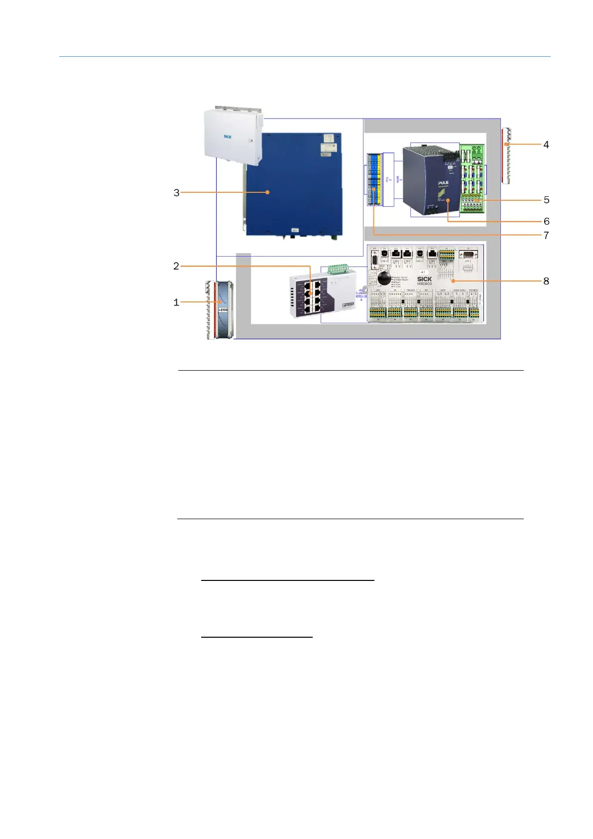
Fig. 5: Components in the cabinet
Legend
1 Air inlet for cooling (with filter mat and cooler)
2 Ethernet switch for connecting the system components
3 VMC800 volume measurement controller
4 Air outlet for cooling (with filter mat)
5 Terminals (24 V DC) and fuse module OUT
6 Power supply unit for supplying voltage to the system components
7 Terminals for voltage supply IN (100–264 V AC / 50–60 Hz)
8 MSC800 system controller
• The power supply unit supplies the voltage to the controllers and connected sensors.
• The VMC800 volume measurement controller receives the measuring points from the
volume measurement devices and uses the 2D sections to calculate a three-
dimensional model. Based on this model, it determines the dimensional values and
transmits these to the MSC800 system controller via CAN bus.
• The MSC800 system controller coordinates all the connected sensors. It processes
the trigger and encoder signals and, via its digital inputs and outputs, provides all the
relevant information for calculating the object dimensions.
The MSC800 receives the measurement results from the VMC800 and outputs these
to the customer system in a defined host telegram.
Function