COMMISSIONING 6
Subject to change without notice
TRANSLATION OF THE ORIGINAL OPERATING INSTRUCTIONS| VMS6200
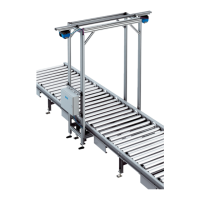
6.2 Checking the operational readiness of the system components
The DEVICE READY LED lights up.
Fig. 30: MSC800 operational readiness
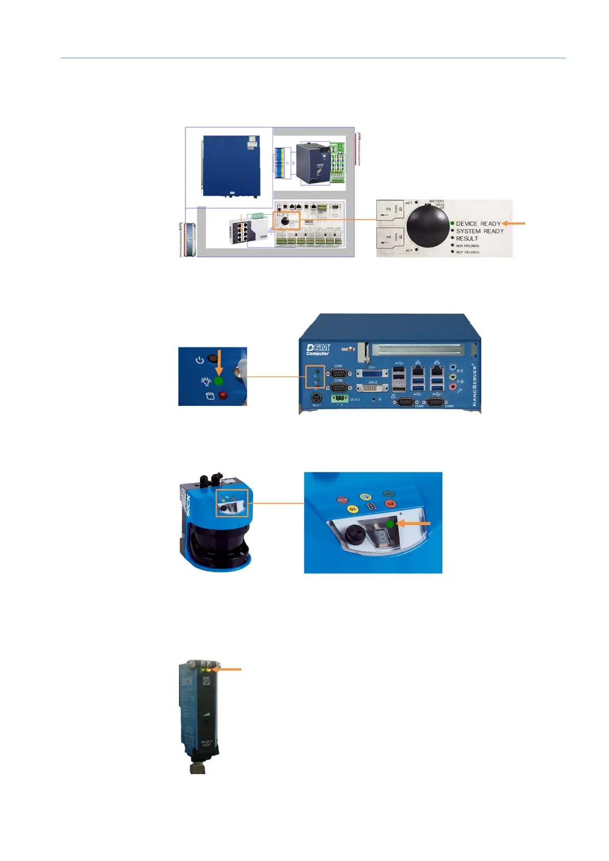
Power LED lights up.
Fig. 31: VMC800 operational readiness
Green LED lights up.
Fig. 32: Operational readiness of the LMS500
▸
The reflector and photoelectric sensor are correctly aligned to one another.
▸
The available sensing range is sufficient.
The green and yellow LED receive indicators light up.
Fig. 33: Operational readiness of the photoelectric retro-reflective sensor (in this case WL-18)
MSC800
VMC800
LMS500
Photoelectric retro-
reflective sensor