6 COMMISSIONING
TRANSLATION OF THE ORIGINAL OPERATING INSTRUCTIONS| VMS6200
Subject to change without notice
6.3.3 Assigning IP addresses
IP addresses in the delivery state:
Volume measurement controller
Tab. 8: Default IP addresses of device components
Recommended CAN and IP address assignments:
VMC800 volume measurement controller
Tab. 9: Recommended addresses of device components
As the IP addresses of the LMS500 and MSC800 are the same, the IP addresses must be
assigned for each device individually.
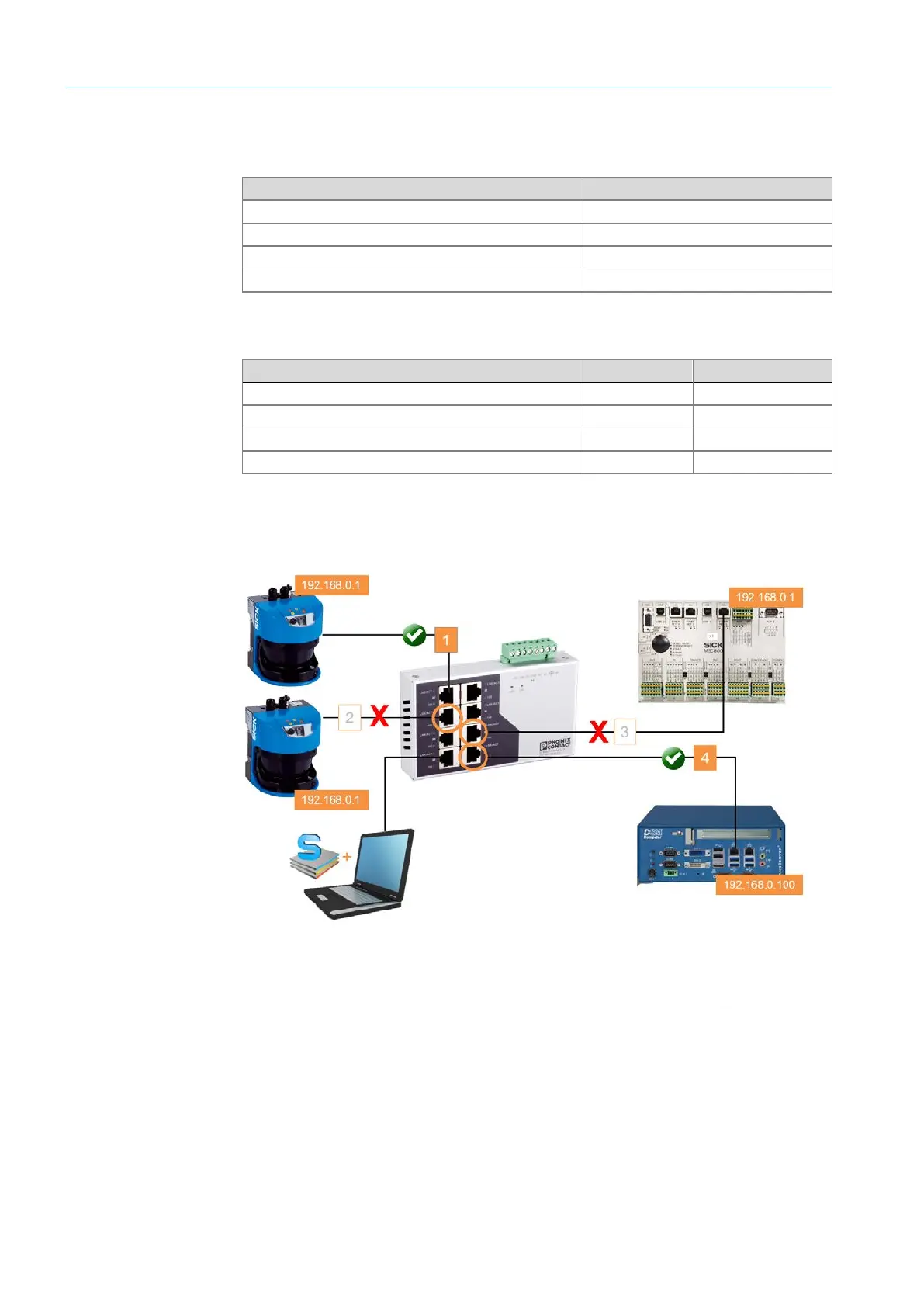
Fig. 35: Procedure for assigning IP addresses
▸
Make sure that the LMS500 sensors are mounted correctly and electrically connected.
▸
Detach all Ethernet connections from the Ethernet switch so that only one LMS500 is
connected to the Ethernet switch.
NOTE! The VMC800 can remain connected to the Ethernet switch.
▸
Connect the configuration PC to a free port on the Ethernet switch
▸
Make sure that the configuration PC is in the number range of the connected device
components.
If it is not, change the IP address of the configuration PC accordingly.
Overview
Procedure