MAINTENANCE AND REPAIR 7
Subject to change without notice
TRANSLATION OF THE ORIGINAL OPERATING INSTRUCTIONS| VMS6200
7.2.5 Replacing the photoelectric retro-reflective sensor
If the VMS6200 is triggered by a photoelectric retro-reflective sensor (e.g., WL18-3), the
sensor should be replaced immediately if defective.
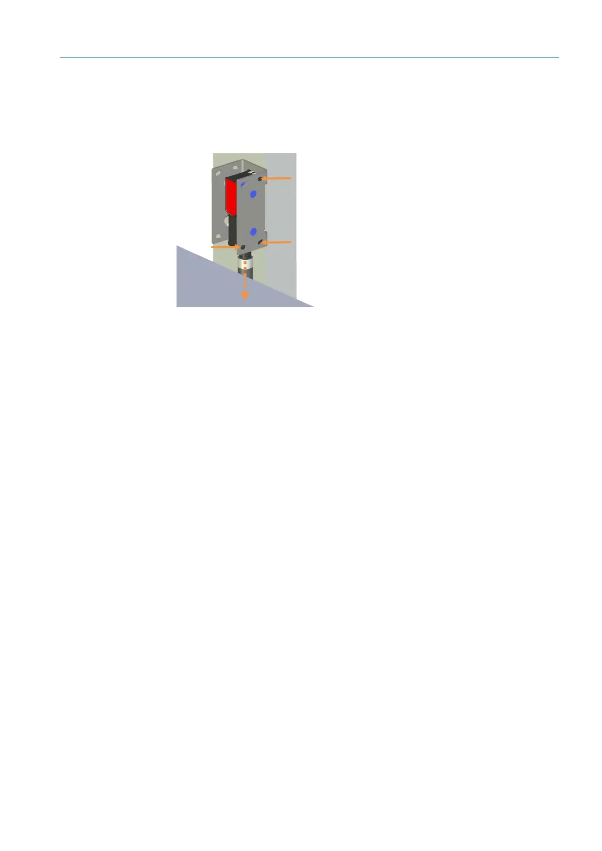
Fig. 51: Replacing the photoelectric retro-reflective sensor
▸
Unscrew the M12 plug connector from the male connector on the photoelectric retro-
reflective sensor.
▸
Loosen and remove the fixing screws.
NOTE! Hold the photoelectric retro-reflective sensor firmly with one hand during the
procedure.
▸
Remove the defective photoelectric sensor from the mounting bracket.
▸
Screw the replacement device onto the mounting bracket.
▸
Screw the M12 plug connector onto the male connector on the photoelectric retro-
reflective sensor.
▸
Align the photoelectric sensor correctly on the reflector. The reflector must be in line
with the beam path of the photoelectric retro-reflective sensor.
Check that the photoelectric retro-reflective sensor is operating correctly.
Replacing the
component