4 MOUNTING
TRANSLATION OF THE ORIGINAL OPERATING INSTRUCTIONS| VMS6200
Subject to change without notice
4.1.1 Mounting components
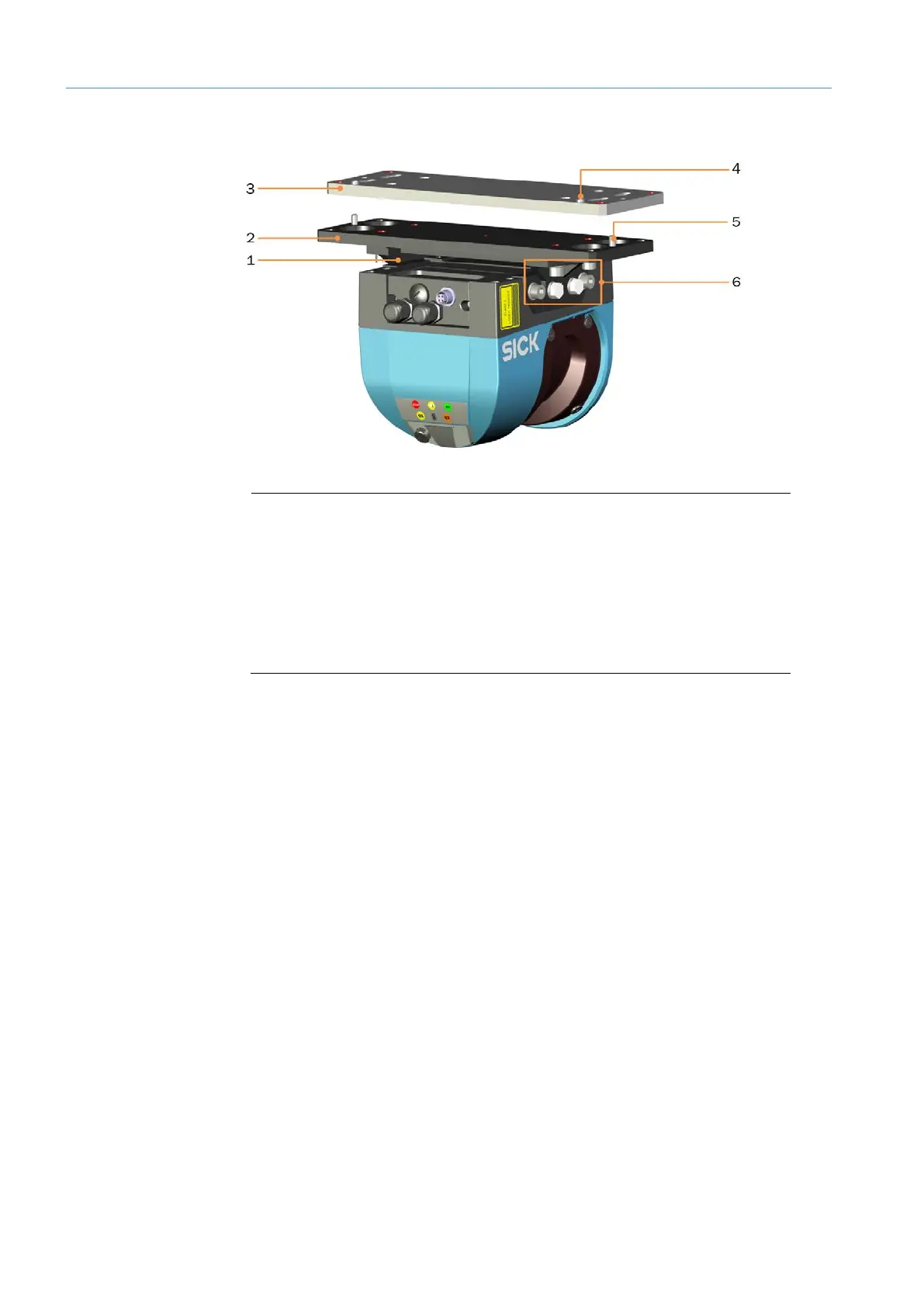
Fig. 17: LMS500 with mounting components
Legend
1 Adjustment unit
2 Adapter plate
3 Mounting plate
4 Stop screw of the mounting plate
5 Guide pin of the adapter plate
6 Mounting screws with locking varnish
• The LMS500, complete with system plug, is pre-mounted on an adapter plate with
adjustment unit at the factory. It has already been adjusted.
• All screws that are used to fasten the LMS500 to the adjustment unit and the adapter
plate have been secured against self-loosening or undesired loosening through the
application of locking varnish to the threaded connections.
NOTE! The threaded connections must not be undone. Otherwise measurements with
the specified accuracy can no longer be guaranteed.
• The unit comprising LMS500, adjustment unit and adapter plate are mounted onto the
frame using the mounting plate included in the scope of delivery.
NOTE! From a technical perspective, both LMS500 sensors are identical. They are
configured as master and slave during commissioning.