8 FAULT DIAGNOSIS
TRANSLATION OF THE ORIGINAL OPERATING INSTRUCTIONS| VMS6200
Subject to change without notice
8.2 Fault indication during operation
8.2.1 Checking the triggering
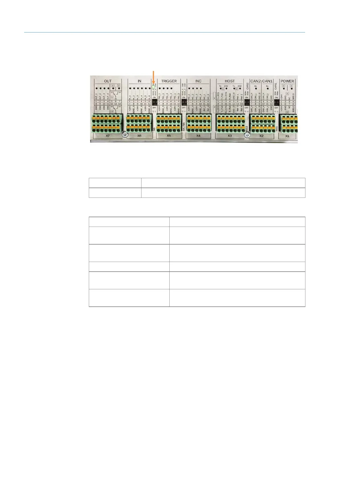
Fig. 55: Checking the triggering on the MSC800
If the read cycle sensor was connected correctly, the following LED must light up on the
system controller:
Controller type LED
MSC800 TRIGGER terminal block, LED on the 1 TRG_1 connection
If the LED does not light up, possible causes might be:
Cause Remedy
Beam path is permanently
interrupted by an object.
Eliminate the permanent interruption by the object.
Photoelectric sensor is not
aligned with the reflector.
Readjust the photoelectric sensor and align it with
the reflector.
Signal ground not activated.
Set the SGND_5 signal ground switch to ON.
Wire is not correctly attached
in the terminal block.
Check that the wires are attached correctly.
Photoelectric sensor is
defective.
Replace the device.
Tab. 15: Checking the triggering on the MSC800