3 SYSTEM DESCRIPTION
TRANSLATION OF THE ORIGINAL OPERATING INSTRUCTIONS| VMS6200
Subject to change without notice
3.3.2 Recording of measured values and data processing
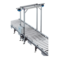
Fig. 10: Measuring point determination of the VMS6200
• The measurement process is activated via the trigger signal.
• The volume measurement devices span a two-dimensional measuring range and scan
the surfaces of the object located within this range on the conveying equipment,
without making contact.
• The volume measurement devices transmit the acquired measuring points to the
VMC800 volume measurement controller.
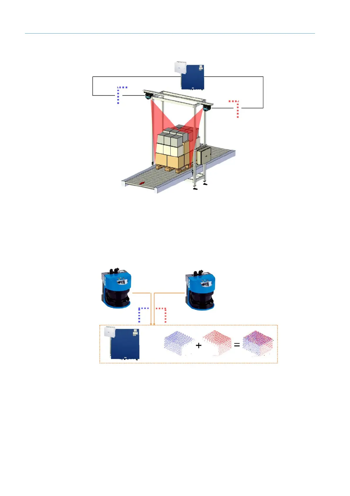
Fig. 11: 3D model generation in the VMC800 volume measurement controller
• There, a spatial model is created taking into consideration the detected conveyor
speed and the specific position of the object on the conveying equipment.
• The VMC800 calculates the volume of the smallest rectangular box that fully encloses
the object and uses this to derive the length, width and height.
• The rotation and position of the object on the conveying equipment is also determined.
• The measurement results are transmitted to the MSC800 system controller for further
processing.